Nissan Micra Distributor Exploded Diagram - Ignition System Construction EL-34
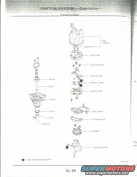
Exploded-parts diagram of a Nissan distributor: cap assembly, carbon point, rotor head, governor spring/weight/plate, pickup coil, IC ignition unit, breaker, and vacuum controller, with high-temperature grease points marked.
This document is a page (EL-34) from a Nissan service manual covering the Ignition System, specifically the distributor. It presents an exploded parts (construction) diagram of a complete distributor assembly, showing the order and relationship of all internal components. Labeled parts include the cap assembly with carbon point, rotor head, governor spring, governor plate, governor weight, governor base, pick-up coil, IC ignition unit, breaker, and vacuum controller, along with the shaft-side components: bearing, shaft, housing, O-ring, collar, and roll pin. Black arrow symbols on the diagram indicate high-temperature grease points, which per the legend appear at the governor weight area and the vacuum controller linkage. The diagram carries the illustration reference code SEL545D. A reader can learn the disassembly/reassembly order of the distributor, the names of each component, and where high-temperature grease must be applied during service. The page appears to belong to a larger multi-page electrical (EL) section scanned by the uploader; adjacent text from the following page is partially visible at the right edge but not legible. No year, model, or engine applicability is stated on this page itself, though it was uploaded as documentation for a 1990 Nissan Micra.
Is this accurate? Sign in to help verify it.
Frequently asked questions
- What components make up the Nissan distributor shown in this diagram?
- The exploded diagram shows the cap assembly with carbon point, rotor head, governor spring, governor plate, governor weight, governor base, pick-up coil, IC ignition unit, breaker, vacuum controller, and the shaft-side parts: bearing, shaft, housing, O-ring, collar, and roll pin.
- Where should high-temperature grease be applied on this distributor?
- The legend states the black arrow symbols mark high-temperature grease points; arrows appear at the governor weight area and at the vacuum controller linkage.
- Does this distributor use points or an electronic ignition module?
- The diagram shows a pick-up coil and an IC ignition unit, indicating an electronic (breakerless-type) ignition with an IC module, along with a component labeled 'breaker' (breaker plate assembly).
- What page and illustration reference is this diagram?
- The page is EL-34 of the manual's electrical section, and the exploded illustration carries reference code SEL545D.
Comments
More from this build











No comments yet.