Ford Bronco Upper Intake Manifold & Throttle Body Exploded Diagram - TPS, IAC

Reference · 1992-1996 BroncoAll 169 exploded parts diagrams
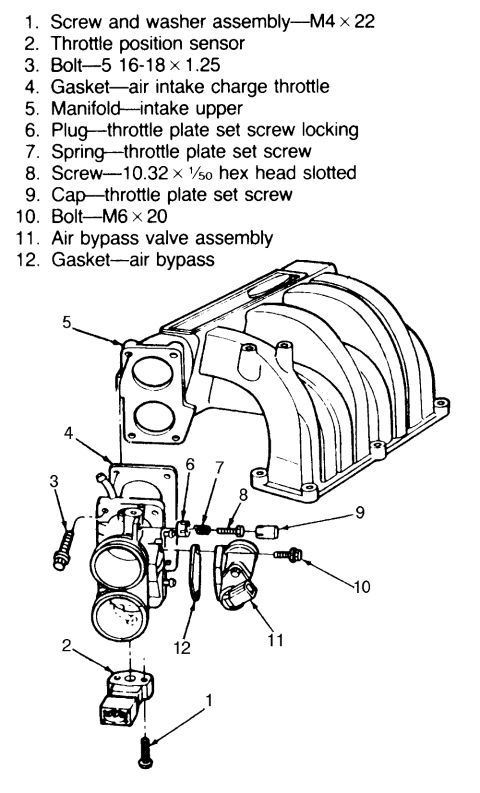

Exploded parts diagram of the upper intake manifold, throttle body, and air bypass valve assembly with a numbered components legend.
Part of 1992-1996 Ford Bronco Exploded Parts Diagrams
This document is an exploded parts diagram of an upper intake manifold and throttle body assembly, uploaded to a 1992 Ford Bronco gallery. It includes a numbered legend identifying twelve components: (1) M4 × 22 screw and washer assembly, (2) throttle position sensor, (3) 5/16-18 × 1.25 bolt, (4) air intake charge throttle gasket, (5) upper intake manifold, (6) throttle plate set screw locking plug, (7) throttle plate set screw spring, (8) 10.32 × 1/50 hex head slotted screw, (9) throttle plate set screw cap, (10) M6 × 20 bolt, (11) air bypass valve assembly, and (12) air bypass gasket. The line drawing shows how these parts relate: the throttle body mounts to the upper intake manifold through a gasket, the throttle position sensor attaches to the bottom of the throttle body with a screw, and the air bypass (idle air) valve mounts to the throttle body through its own gasket with an M6 × 20 bolt. A reader can learn the assembly order, fastener sizes, and gasket locations needed to remove or reinstall the throttle body, TPS, and air bypass valve on this intake system. The document itself carries no year, model, or engine identification.
Is this accurate? Sign in to help verify it.
Frequently asked questions
- What size are the throttle position sensor mounting screws?
- The diagram lists item 1 as a screw and washer assembly, size M4 × 22, which attaches the throttle position sensor (item 2).
- What bolt holds the air bypass valve assembly to the throttle body?
- Item 10, an M6 × 20 bolt, secures the air bypass valve assembly (item 11), which mounts with an air bypass gasket (item 12).
- What gasket goes between the throttle body and the upper intake manifold?
- Item 4, the gasket, air intake charge throttle, sits between the throttle body and the upper intake manifold (item 5).
- What parts make up the throttle plate set screw arrangement?
- The throttle plate set screw hardware includes a locking plug (item 6), a spring (item 7), a 10.32 × 1/50 hex head slotted screw (item 8), and a cap (item 9).
- What size bolt attaches the throttle body assembly?
- Item 3 is listed as a bolt, 5 16-18 × 1.25 (5/16-18 × 1.25).



No comments yet.