1992 Ford 5.0L/5.8L Engine Component Connector Locations Diagram - Bronco/F-Series

Reference · 1992-1996 BroncoAll 95 schematics
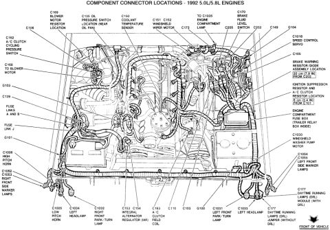



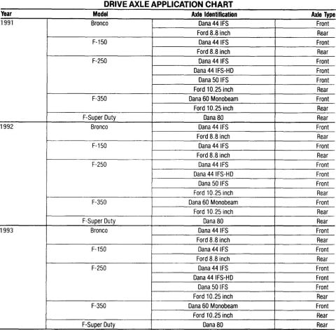
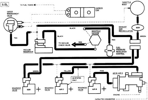
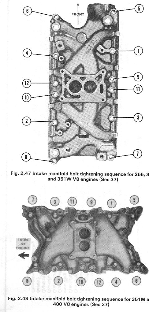



Component connector location schematic for 1992 Ford 5.0L/5.8L engines identifying sensors, modules, and connector IDs.
Part of 1992-1996 Ford Bronco Schematics
This document is a factory-style engine compartment schematic titled "Component Connector Locations - 1992 5.0L/5.8L Engines," showing a top-down illustration of the engine bay for Ford vehicles equipped with the 5.0L or 5.8L V8. Each labeled callout identifies the physical location of an electrical connector or component: starter motor and solenoid (C116), starter relay, MAP sensor (C1011), knock sensor connector (C1009, 5.0L only), thermactor air bypass and diverter solenoids (C1022 TAB round, C1023 TAD square), EGR control solenoid (C180), ignition coil (C1008), radio capacitor, DSS test connector (C143), EEC module (C185), VIP test connectors (C198/C199), TFI ignition module (C1021), SPOUT check connector (C1019), HEGO sensor (5.0L and 5.8L under 8500 GVW only), EVP sensor (C182), ACT sensor (C164), power steering pressure switch (C1016, 5.0L only), TPS, canister purge solenoid (C171), ECT sensor (C183), idle air bypass valve (C1007), the eight fuel injector connectors (C190-C197), distributor, and several harness connectors (C101, C178, C1003, C1017, C1024, C1025). An arrow indicates the front of the vehicle. A reader can use this to locate any of these engine-management connectors for diagnostics or repair.
Is this accurate? Sign in to help verify it.
Frequently asked questions
- Where are the fuel injector connectors on the 1992 5.0L/5.8L engine?
- Connectors C190, C191, C192, C193, C194, C195, C196 and C197 are the eight fuel injector connectors, located along the intake area near the center-rear of the engine (labeled '1 of 8' in the diagram).
- What connector is the SPOUT check connector on a 1992 5.0L/5.8L?
- C1019 is the SPOUT check connector, located on the passenger side near the TFI ignition module (C1021).
- Which connectors are the diagnostic test connectors?
- C143 is the DSS test connector, and C198/C199 are the VIP test connectors, both located on the passenger side of the engine compartment near the EEC module (C185).
- How do I tell the TAB and TAD solenoids apart?
- Per the diagram, the C1022 Thermactor Air Bypass (TAB) solenoid is round and the C1023 Thermactor Air Diverter (TAD) solenoid is square.
- Are all callouts on this diagram valid for both 5.0L and 5.8L engines?
- No. The C1009 knock sensor connector and C1016 power steering pressure switch apply to the 5.0L only, and the HEGO sensor and C1025 apply to 5.0L and 5.8L under 8500 GVW only.






No comments yet.