Caster Angle Diagram - Ford Solid Axle Radius Arm & C-Bushing Steering Geometry

Reference · 1992-1996 BroncoAll 95 schematics
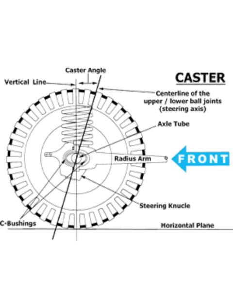



Schematic diagram explaining front-suspension caster angle geometry with steering axis, axle tube, radius arm, and ball joints.
Part of 1992-1996 Ford Bronco Schematics
This document is a labeled schematic diagram illustrating the concept of caster angle in a vehicle's front suspension/steering geometry, drawn as a side view of a front wheel with a coil spring, axle, and radius arm. The diagram shows a vertical reference line passing through the wheel and a slanted line labeled as the centerline of the upper/lower ball joints (the steering axis); the angle between these two lines at the top is labeled 'Caster Angle.' A horizontal plane line runs beneath the tire to establish the ground reference. Callout arrows identify key suspension components: the Axle Tube at the wheel center, the Radius Arm extending toward the front of the vehicle (indicated by a large 'FRONT' arrow pointing right), the Steering Knuckle below the axle, and the C-Bushings where the radius arm mounts. The diagram teaches a reader how caster is defined, the tilt of the steering axis relative to vertical when viewed from the side, and which physical parts (radius arm, C-bushings) relate to setting or adjusting caster on this style of solid front axle suspension. No year, make, model, part numbers, or specification values are given in the document itself.
Is this accurate? Sign in to help verify it.
Frequently asked questions
- What is the caster angle in this diagram?
- It is the angle measured between the vertical line and the centerline of the upper/lower ball joints (the steering axis), viewed from the side of the wheel.
- What defines the steering axis in this suspension diagram?
- The centerline drawn through the upper and lower ball joints is labeled as the steering axis.
- Which components are labeled in the caster diagram?
- The diagram labels the Axle Tube, Radius Arm, Steering Knuckle, C-Bushings, the vertical line, the steering-axis centerline, and the horizontal plane.
- Which direction is the front of the vehicle in the diagram?
- A large arrow labeled 'FRONT' points to the right, in the direction the radius arm extends.
- Where are the C-Bushings located in the diagram?
- The C-Bushings callout points to the area near the lower portion of the axle/wheel assembly, where the radius arm connects at the axle.






No comments yet.