Ford Bronco Drum Brake Self-Adjuster Operation Diagram - Star Wheel Action
Reference · 1992-1996 BroncoAll 95 schematics
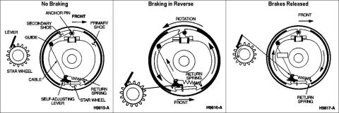


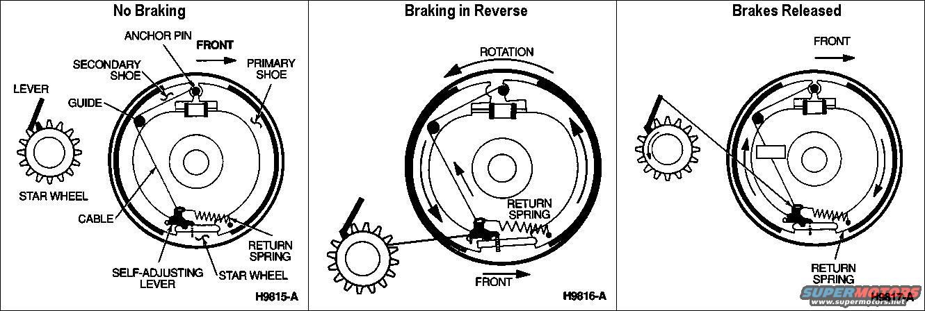
Schematic of drum brake self-adjusting mechanism shown in no-braking, braking-in-reverse and brakes-released states.
Part of 1992-1996 Ford Bronco Schematics
This schematic illustrates the operation of a drum brake self-adjuster mechanism in three sequential panels: 'No Braking', 'Braking in Reverse', and 'Brakes Released'. Each panel shows a cross-sectional view of a drum brake assembly with an enlarged inset of the star wheel adjuster. The first panel identifies the key components: anchor pin, secondary shoe, primary shoe, guide, cable, return spring, self-adjusting lever, star wheel, and lever, with an arrow indicating the front of the vehicle. The second panel shows drum rotation direction while braking in reverse, illustrating how the shoes shift with the rotating drum and how the cable pulls the self-adjusting lever up over the star wheel against the return spring. The third panel shows the mechanism after the brakes are released, with the return spring pulling the self-adjusting lever back down, rotating the star wheel one notch and thereby lengthening the adjuster to compensate for shoe lining wear. Figure reference numbers H9815-A, H9816-A, and H9817-A identify each illustration. A reader can learn the names and positions of the self-adjuster components and understand why drum brakes self-adjust when braking in reverse.
Is this accurate? Sign in to help verify it.
Frequently asked questions
- When does the drum brake self-adjuster operate?
- According to the diagram, the self-adjusting mechanism acts when braking in reverse; the sequence shown is 'No Braking', 'Braking in Reverse', and 'Brakes Released'.
- What parts make up the drum brake self-adjusting mechanism?
- The diagram labels the anchor pin, secondary shoe, primary shoe, guide, cable, return spring, self-adjusting lever, star wheel, and lever.
- What moves the self-adjusting lever on the star wheel?
- The cable actuates the self-adjusting lever, and the return spring pulls it back when the brakes are released, as shown in the three panels.
- Which direction does the drum rotate during self-adjustment in this diagram?
- The 'Braking in Reverse' panel shows the rotation arrow pointing opposite the vehicle's front direction, indicating reverse drum rotation during adjustment.




No comments yet.