Ford Axle Gear Shimming Diagram - Pinion Depth & Backlash Adjustment

Reference · 1992-1996 BroncoAll 95 schematics
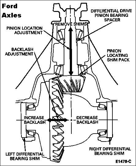


Cutaway schematic of a Ford axle differential labeling pinion location, backlash adjustment and bearing shim locations.
Part of 1992-1996 Ford Bronco Schematics
This document is a labeled cross-section schematic titled "Ford Axles" illustrating gear shimming and adjustment points inside a Ford differential/axle assembly. The diagram shows the drive pinion and ring gear in cutaway view with callouts identifying key adjustment components: the differential drive pinion bearing spacer, the pinion locating shim pack, and the left and right differential bearing shims. Arrows indicate the direction of adjustments: a vertical double-headed arrow labeled "REMOVE SHIMS" shows the pinion location adjustment axis, while a horizontal double-headed arrow shows the backlash adjustment, marked "INCREASE BACKLASH" toward the left differential bearing shim side and "DECREASE BACKLASH" toward the right differential bearing shim side. A reader can learn where shims are located in the axle assembly, which shims control pinion depth versus ring gear backlash, and in which direction the differential case must be shifted (by transferring shims between sides) to increase or decrease backlash. The figure carries the reference number E1476-C. No specific year, model, torque values, or part numbers are given; it is a generic Ford axle gear-setup reference, uploaded to a 1992 Ford Bronco gallery as part of a service documentation set.
Is this accurate? Sign in to help verify it.
Frequently asked questions
- What adjusts the pinion location in a Ford axle?
- The diagram shows pinion location adjustment is made via the pinion locating shim pack and the differential drive pinion bearing spacer, with an arrow labeled 'REMOVE SHIMS' along the pinion axis.
- How is ring gear backlash adjusted according to this diagram?
- Backlash is adjusted using the left and right differential bearing shims; moving toward the left differential bearing shim increases backlash, and moving toward the right differential bearing shim decreases backlash.
- Which shims control backlash versus pinion depth?
- The left and right differential bearing shims control backlash, while the pinion locating shim pack (with the differential drive pinion bearing spacer) controls pinion location/depth.
- What is the figure reference number on this Ford axle diagram?
- The diagram carries the reference number E1476-C.
No comments yet.