Nissan Micra Charging System Wiring Diagram - Alternator & Charge Lamp (EL-23)
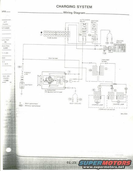
Factory charging-system wiring diagram showing the alternator (IC regulator built in to rival), fusible link, battery, auto-choke/ignition relays and charge-lamp circuit; covers with- and without-tachometer combination meters.
This is a scanned service-manual page titled "CHARGING SYSTEM: Wiring Diagram" (page EL-23, diagram reference SEL506I). It shows the complete charging circuit wiring, including the battery, fusible link, alternator (IC regulator built-in type) with terminals B, L, S, E, the fuse block with two 15A fuses, an auto-choke relay, an ignition relay, and the ignition switch with a continuity table for OFF/ACC/ON/ST positions. Wire color codes are labeled throughout, including W/L, W/R, W, Y, G/Y, B, and R, along with numbered harness connectors such as 16M, 52M, 13M, 55M, 71M, 14M, 7M, 54M, 1I, and 6I. The diagram distinguishes between main harness and instrument harness sections and shows two charge-lamp configurations within the combination meter: one for models with a tachometer (T) and one without (WO). Body ground points are indicated. The left margin contains partial specification text from an adjacent page (A/T models, gap values like 0.3-2.5 mm / 0.012-0.098 in). A reader can trace the alternator charge circuit, identify connector numbers and wire colors for diagnosis, and verify ignition switch position continuity for troubleshooting a no-charge or charge-lamp problem.
Is this accurate? Sign in to help verify it.
Frequently asked questions
- What type of alternator is shown in this charging system wiring diagram?
- An alternator with an IC regulator built-in type, with terminals B, L, S, and E connecting through connector 7M and related harness wiring.
- What wire colors are used in the charging system circuit?
- The diagram labels wires as W/L, W/R, W, Y, G/Y, B, and R (fusible link), running between the fuse block, relays, ignition switch, alternator, and combination meter.
- How is the charge lamp wired for models with and without a tachometer?
- The combination meter shows two charge lamp configurations: (T) with tachometer using Y and W/R wires, and (WO) without tachometer using Y and W/R wires through connector 6I.
- What relays are involved in this charging circuit?
- An auto-choke relay and an ignition relay, both fed from the fuse block via 15A fuses.
- What connectors are shown in the charging system diagram?
- Numbered connectors include 16M, 52M, 13M, 55M, 71M, 14M, 7M, 54M, 1I, and 6I, spanning the main harness and instrument harness.
Comments
More from this build











No comments yet.