Nissan Micra Combination Switch Check & Continuity Tables - EL-38 Diagram
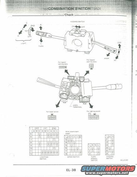
Combination switch diagram showing lighting, turn, wiper and hazard terminals with continuity charts for each switch position.
This is page EL-38 of a Nissan electrical service manual section covering the combination switch (steering column stalk switch) check procedure. The top illustration shows the combination switch assembly with lever positions labeled: the lighting switch rotates through OFF, 1ST, and 2ND with lever positions A, B, C; the turn signal lever moves to R, N, and L; the hazard switch slides between ON and OFF; and the wiper stalk operates OFF, INT, LO, HI plus WASH. A second illustration shows the back of the switch body, identifying the horn terminal and four connectors with their pin numbering: hazard warning lamp connectors (pins 21-27), the wiper switch connector (pins 13-18), and the lighting switch connector (pins 1-12). Below are four continuity test tables used to check the switch with an ohmmeter: the lighting switch table (terminals 5-12 across OFF/1ST/2ND positions A, B, C), the intermittent wiper switch table (terminals 13-18 across OFF/INT/LO/HI/WASH), the turn signal switch table (terminals 1-3 across R/N/L), and the hazard switch table (terminals 21-26 across OFF/ON). Figure reference SEL518D. A reader can identify connector pin locations and expected continuity for testing each function of the combination switch.
Is this accurate? Sign in to help verify it.
Frequently asked questions
- What connector pins are used for the wiper switch on this combination switch?
- The wiper switch connector uses pins 17, 14, 13, 16 on the top row and 18 and 15 on the bottom row (two positions are marked X/unused). The continuity table covers terminals 13-18 across OFF, INT, LO, HI, and WASH positions.
- Which terminals belong to the turn signal switch and what positions are tested?
- Terminals 1, 2, and 3 are tested in the R (right), N (neutral), and L (left) lever positions per the turn signal switch continuity table.
- What are the hazard switch terminals shown on this page?
- The hazard switch continuity table lists terminals 21 through 26, tested in OFF and ON positions. The hazard warning lamp connectors are shown with pins 26/25/24 and 21/23/27/22.
- What lever positions does the lighting switch have?
- The lighting switch rotates through OFF, 1ST, and 2ND, each with lever positions A, B, and C; the continuity table covers terminals 5 through 12.
- Where is the horn terminal on the combination switch?
- The horn terminal is called out on the rear-view illustration of the combination switch body, located at the center-bottom area of the switch near the steering shaft opening.
Comments
More from this build











No comments yet.