Home/
Registry/
Nissan/
Micra/
1983-1992/
1990 Nissan Micra/
Photo
supermotors.net/registry/media/294121
Nissan Micra Horn, Cigarette Lighter & Clock Wiring Diagram (EL-54)

Reference · 1983-1992 MicraAll 23 wiring diagrams

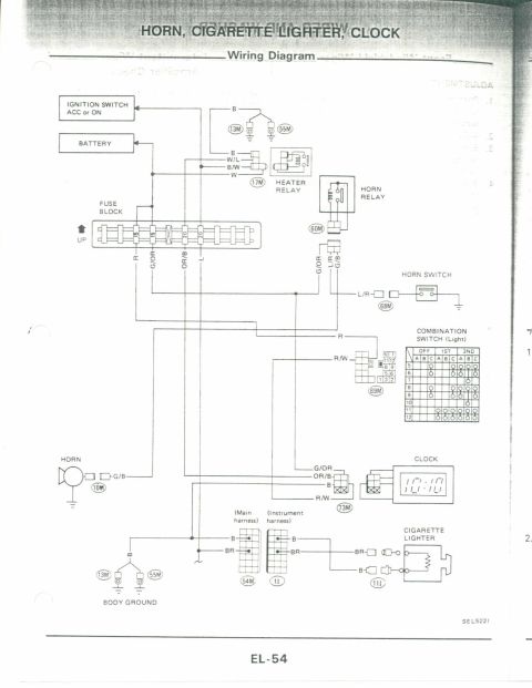
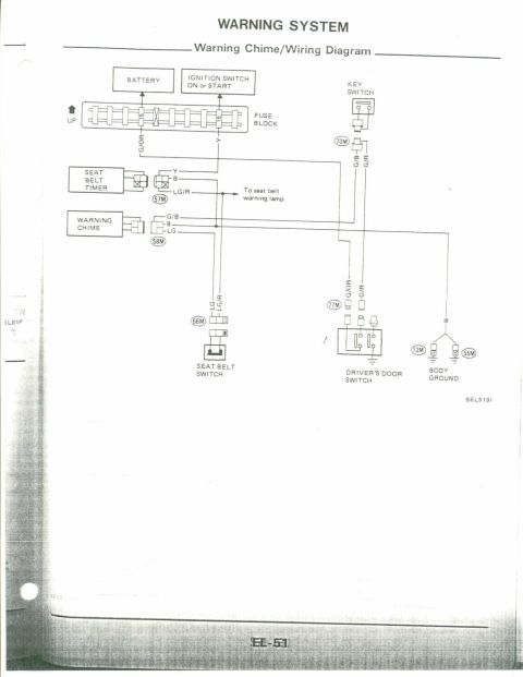
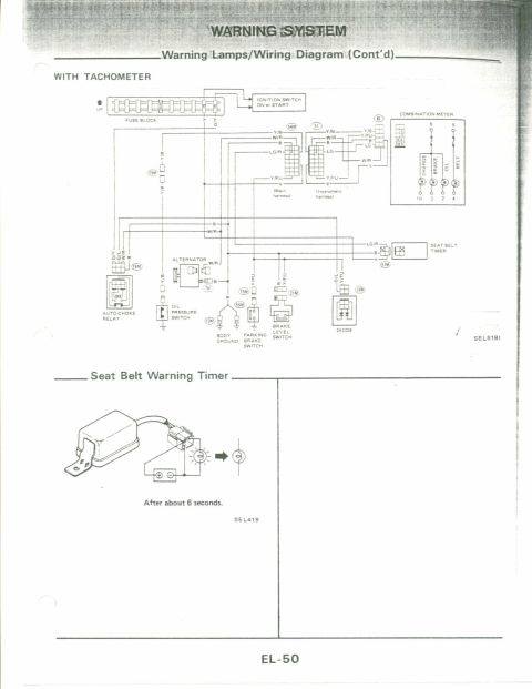
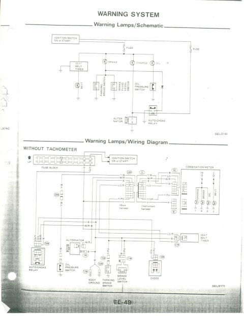

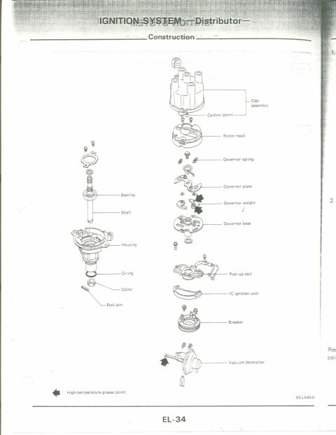
Wiring diagram for horn, cigarette lighter and clock circuits: ignition switch, battery, fuse block, heater relay, horn relay, horn switch, combination switch and body grounds.
Part of 1983-1992 Nissan Micra Wiring Diagrams
This is page EL-54 from a Nissan factory service manual electrical section, showing the combined wiring diagram for the horn, cigarette lighter, and clock circuits. Power originates from the battery and the ignition switch (ACC or ON positions) and passes through the fuse block, which shows fuses rated 15A, 15A, 20A, and 20A feeding wires colored R, G/OR, OR/B, and L. The diagram traces the horn circuit through the horn relay (connector 60M) and horn switch (68M) via an L/R wire to ground, with the horn itself fed by a G/B wire at connector 10M. A heater relay (17M) is also shown on the shared feed. The combination light switch (69M) is documented with a pin layout and a continuity table showing which of pins 5-12 are connected in the OFF, 1ST, and 2ND positions across columns A, B, and C. The clock (73M) receives G/OR, OR/B, B, and R/W wires. The cigarette lighter is fed BR and B wires through main harness (54M) and instrument harness (1I/1II) connectors, with body grounds at connectors 13M and 55M. Diagram reference number SEL522I appears at bottom right.
Is this accurate? Sign in to help verify it.
Frequently asked questions
- What fuse ratings protect the horn, cigarette lighter, and clock circuits?
- The fuse block in the diagram shows fuses rated 15A, 15A, 20A, and 20A feeding wires colored R, G/OR, OR/B, and L for these circuits.
- What wire color goes from the horn relay to the horn switch?
- An L/R (blue/red) wire runs from the horn relay through connector 68M to the horn switch, which grounds the circuit.
- What wire colors connect to the clock?
- The clock connector (73M) receives G/OR, OR/B, B, and R/W wires.
- How is the cigarette lighter wired?
- The cigarette lighter receives a BR wire (via connector 1II) and a B wire, routed through the main harness connector 54M and instrument harness connector 1I, with body grounds at connectors 13M and 55M.
- What connector numbers are shown in this diagram?
- Connectors shown include 10M (horn), 13M and 55M (body grounds), 17M (heater relay), 54M, 60M (horn relay), 68M (horn switch), 69M (combination switch), 73M (clock), 1I, and 1II (cigarette lighter).


No comments yet.