Home/
Registry/
Nissan/
Micra/
1983-1992/
1990 Nissan Micra/
Photo
supermotors.net/registry/media/294122
Nissan Micra Rear Window Defogger Wiring Diagram & Filament Check (EL-55)

Reference · 1983-1992 MicraAll 23 wiring diagrams


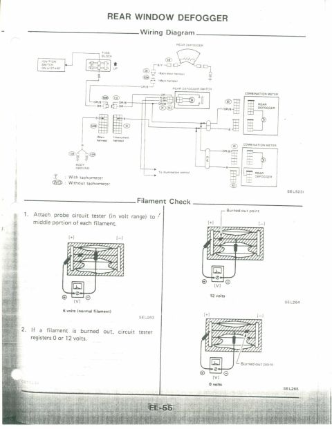

Factory rear-window defogger wiring diagram plus filament-check procedure: a good filament reads ~6V at mid-point on a volt tester, a burned-out filament reads 0 or 12 volts.
Part of 1983-1992 Nissan Micra Wiring Diagrams
This is page EL-55 from a Nissan factory service manual (Electrical section), covering the Rear Window Defogger system. The top half presents the wiring diagram for the rear defogger circuit: power flows from the ignition switch (ON or START position) through the fuse block, via orange (OR) and orange/black (OR/B) wires to the rear defogger switch, then via a B/Y wire through the back door harness to the rear defogger grid, which is grounded. The diagram shows connector numbers (48, 28, 83M, 89M, 131, 71, 141, 54M, 11, 13M, 55M, 61, 19), body ground points, an illumination control branch, and two combination meter indicator variants, with tachometer (T) and without tachometer (WO). The lower half explains the Filament Check procedure: attach a circuit tester (volt range) probe to the middle of each filament; a normal filament reads 6 volts, while a burned-out filament causes the tester to read 12 volts (break on ground side) or 0 volts (break on power side), with illustrations SEL263, SEL264, and SEL265 showing burned-out point locations. Diagram reference SEL523I appears on the wiring diagram.
Is this accurate? Sign in to help verify it.
Frequently asked questions
- What voltage should a normal rear defogger filament read at its middle point?
- With a circuit tester (in volt range) attached to the middle portion of the filament, a normal filament reads 6 volts.
- How do I know if a rear defogger filament is burned out?
- If a filament is burned out, the circuit tester registers 0 or 12 volts instead of 6 volts. 12 volts indicates the burned-out point is between the probe and the negative side; 0 volts indicates the break is toward the positive side.
- Where does the rear defogger circuit get its power?
- From the ignition switch in the ON or START position, through the fuse block, then through the rear defogger switch to the defogger grid via the back door harness.
- What wire colors are used in the rear defogger circuit?
- The diagram shows OR (orange) and OR/B (orange/black) feed wires, a B/Y wire to the rear defogger through the back door harness, B (black) ground wires, and R/W and G/W wires at the defogger switch.
- Does the wiring differ between tachometer and non-tachometer models?
- Yes. The diagram shows two combination meter versions: (T) with tachometer and (WO) without tachometer, each with its own rear defogger indicator wiring.


No comments yet.