Home/
Registry/
Nissan/
Micra/
1983-1992/
1990 Nissan Micra/
Photo
supermotors.net/registry/media/294115
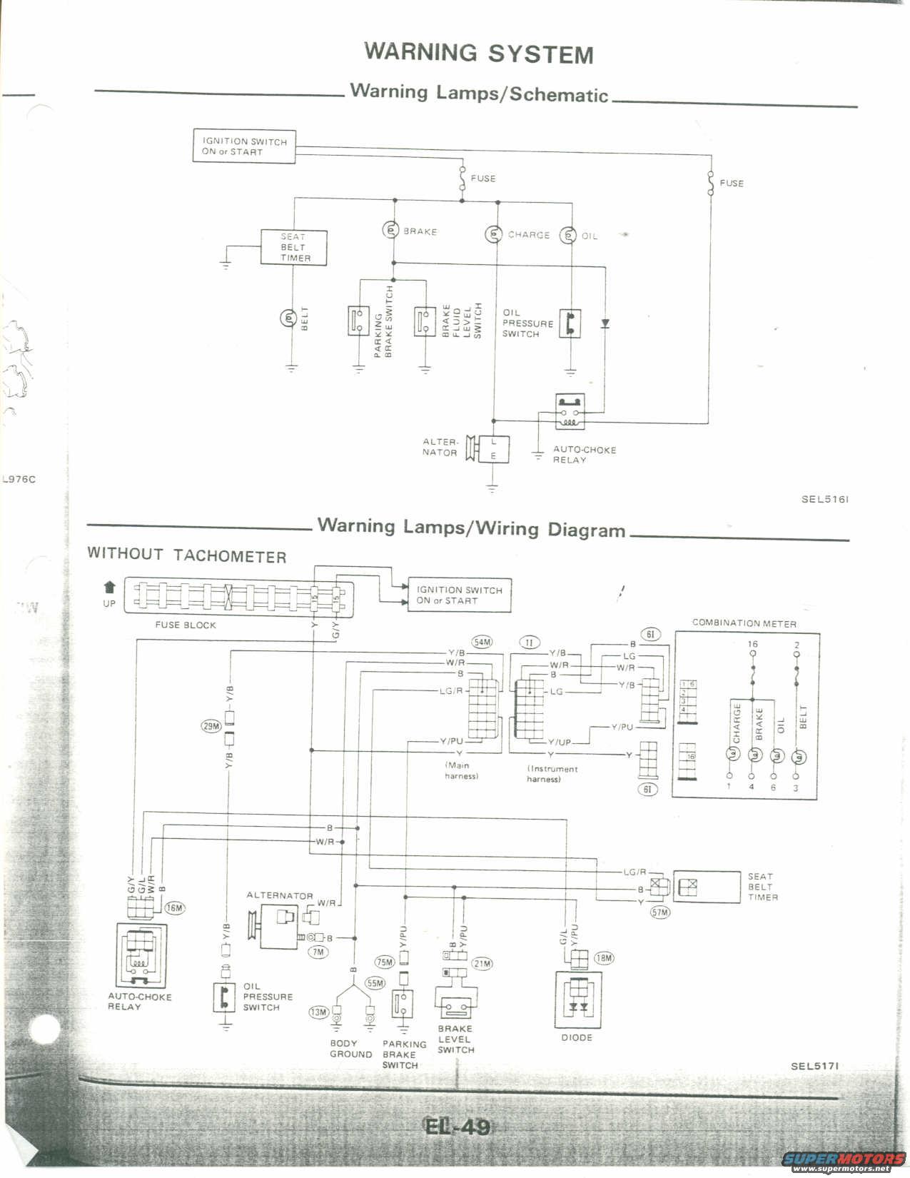
Nissan Warning Lamps Wiring Diagram & Schematic (EL-49) - Charge, Oil, Brake, Belt
Reference · 1983-1992 MicraAll 23 wiring diagrams
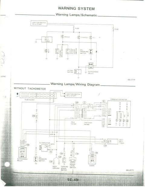
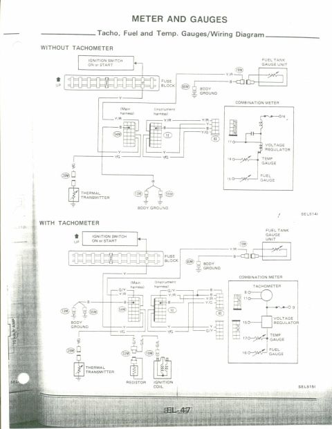
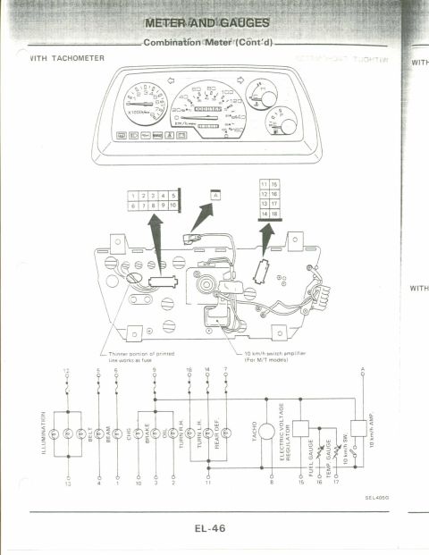
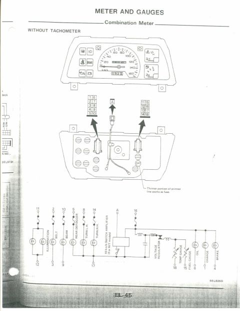

Factory warning-system page: warning-lamp schematic and wiring diagram covering oil-pressure switch, brake/parking-brake and fluid-level switches, charge lamp, seat-belt timer and auto-choke relay.
Part of 1983-1992 Nissan Micra Wiring Diagrams
This scanned service manual page (page EL-49) covers the vehicle's Warning System. The top half presents a simplified schematic (figure SEL516I) of the warning lamps circuit: power flows from the ignition switch (ON or START) through fuses to the BRAKE, CHARGE, OIL and BELT warning lamps. These lamps are grounded through the parking brake switch, brake fluid level switch, oil pressure switch, alternator (L and E terminals), seat belt timer, and an auto-choke relay with a diode. The bottom half is the detailed Warning Lamps/Wiring Diagram for models WITHOUT TACHOMETER (figure SEL517I), showing the fuse block, ignition switch feed, combination meter with CHARGE, BRAKE, OIL and BELT bulbs (pins 16, 2, 1, 4, 6, 3), and harness connectors identified as 54M, 11, 61, 29M, 16M, 7M, 75M, 55M, 13M, 21M, 18M and 57M. Wire color codes are given throughout, including Y, G/Y, Y/B, W/R, B, LG, LG/R, Y/PU, G/L, and G/Y, tracing circuits to the alternator, oil pressure switch, parking brake switch, brake level switch, diode, body ground, auto-choke relay and seat belt timer. A reader can use this page to trace and troubleshoot the warning-lamp circuits by connector number and wire color.
Is this accurate? Sign in to help verify it.
Frequently asked questions
- What warning lamps are shown on this wiring diagram?
- The diagram covers four combination-meter warning lamps: BRAKE, CHARGE, OIL and BELT.
- Which switches control the warning lamps in this circuit?
- The parking brake switch and brake fluid level switch (brake level switch) ground the BRAKE lamp, the oil pressure switch controls the OIL lamp, the alternator L/E terminals control the CHARGE lamp, and a seat belt timer controls the BELT lamp. An auto-choke relay and diode are also in the circuit.
- What wire colors are used in the warning lamp circuits?
- Colors shown include Y, G/Y, Y/B, W/R, B, LG, LG/R, Y/PU and G/L.
- Which harness connectors are identified in the diagram?
- Connectors labeled 54M (main harness), 11 (instrument harness), 61, 29M, 16M, 7M, 75M, 55M, 13M, 21M, 18M and 57M.
- Does this diagram apply to models with a tachometer?
- The wiring diagram shown is labeled 'WITHOUT TACHOMETER'; a separate diagram would apply to tachometer-equipped models.


No comments yet.