Home/
Registry/
Nissan/
Micra/
1983-1992/
1990 Nissan Micra/
Photo
supermotors.net/registry/media/294117
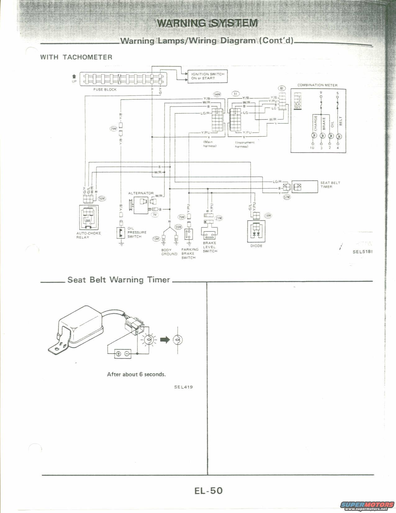
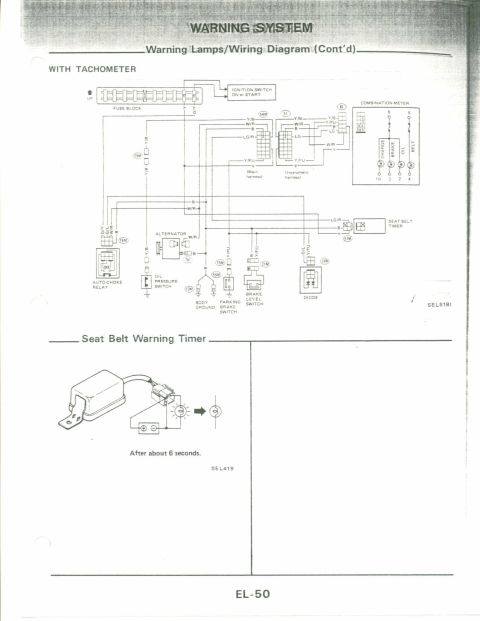
Nissan Warning Lamps Wiring Diagram (With Tachometer) & Seat Belt Timer EL-50
Reference · 1983-1992 MicraAll 23 wiring diagrams
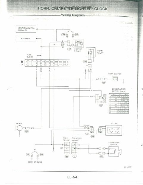
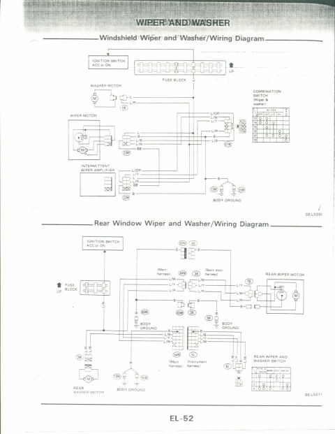
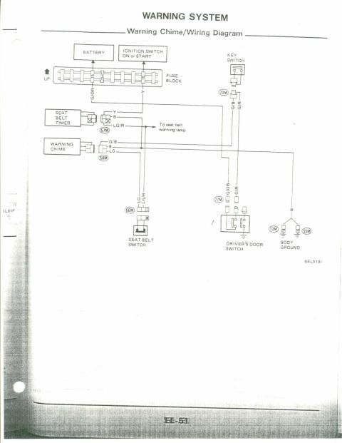
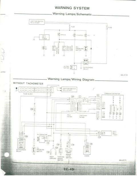
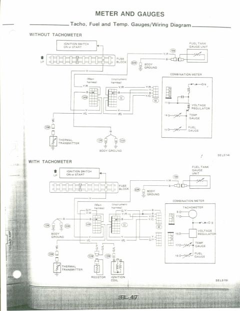
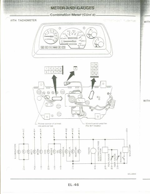
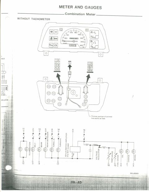

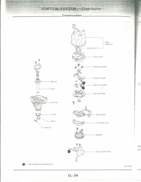
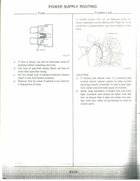
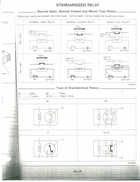
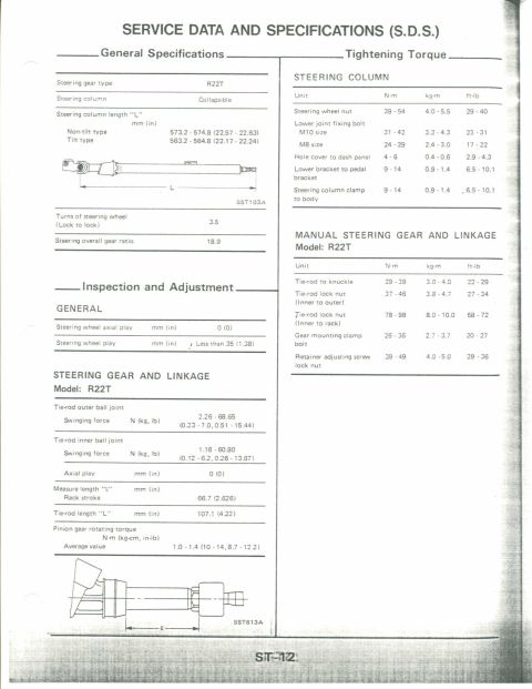
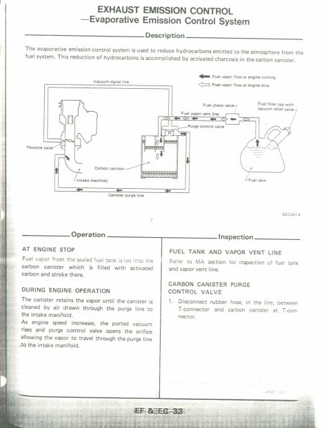
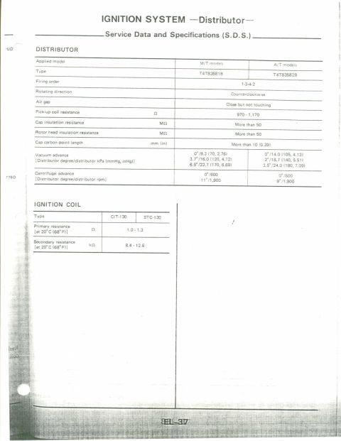
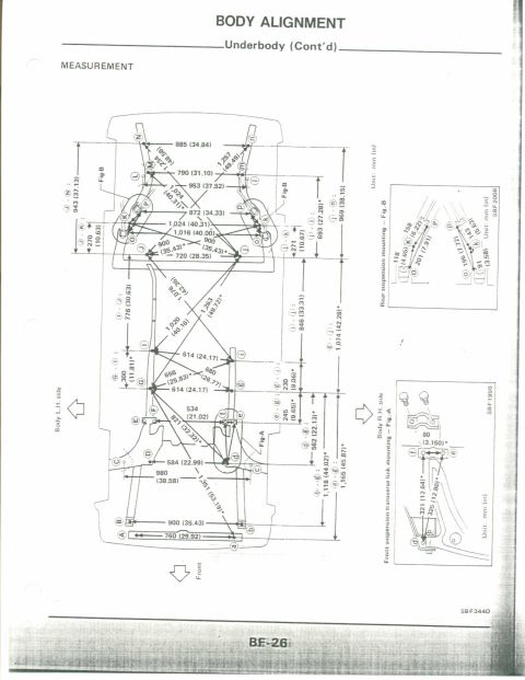
Warning-system wiring diagram showing warning lamps, fuse block, switches and seat-belt timer connections.
Part of 1983-1992 Nissan Micra Wiring Diagrams
This scanned service manual page (EL-50) from the Electrical section covers the Warning System, specifically the continuation of the Warning Lamps/Wiring Diagram for models WITH TACHOMETER. The main wiring diagram traces circuits from the fuse block and ignition switch (ON or START) through the main harness and instrument harness connectors (54M, 11, 61) to the combination meter, which houses the CHARGE, BRAKE, OIL, and BELT warning lamps. Wire color codes shown include Y/B, W/R, B, LG/R, LG, Y/PU, Y, G/Y, and G/L. Components in the circuit include the auto-choke relay, alternator (connector 7M), oil pressure switch, body ground (13M), parking brake switch (55M/75M), brake (fluid) level switch (21M), a diode (18M), and a seat belt timer (57M). A second illustrated section, 'Seat Belt Warning Timer,' shows the timer unit bench-test setup with a battery and lamp, noting the warning lamp goes out 'After about 6 seconds.' Illustration reference numbers SEL518I and SEL419 appear on the page. This document is useful for diagnosing warning lamp circuits (charge, oil, brake, seat belt) and testing the seat belt warning timer.
Is this accurate? Sign in to help verify it.
Frequently asked questions
- What warning lamps are shown in the combination meter on this wiring diagram?
- The combination meter includes CHARGE, BRAKE, OIL, and BELT warning lamps.
- How long does the seat belt warning timer keep the lamp on?
- The illustration shows the seat belt warning lamp goes out after about 6 seconds.
- What switches feed the brake warning lamp circuit in this diagram?
- The diagram shows a parking brake switch and a brake level switch, connected through connectors 55M/75M and 21M, plus a diode at connector 18M.
- What wire colors connect to the seat belt timer?
- The seat belt timer connects via LG/R, B, and Y wires at connector 57M.
- What powers the warning lamp circuit?
- Power comes from the fuse block via the ignition switch in the ON or START position, with Y and G/Y wires leaving the fuse block.


No comments yet.