Turn Signal & Stop Light Switch Wiring Diagram - Flasher Circuit Schematic
Reference · 1992-1996 F-150All 11 wiring diagrams

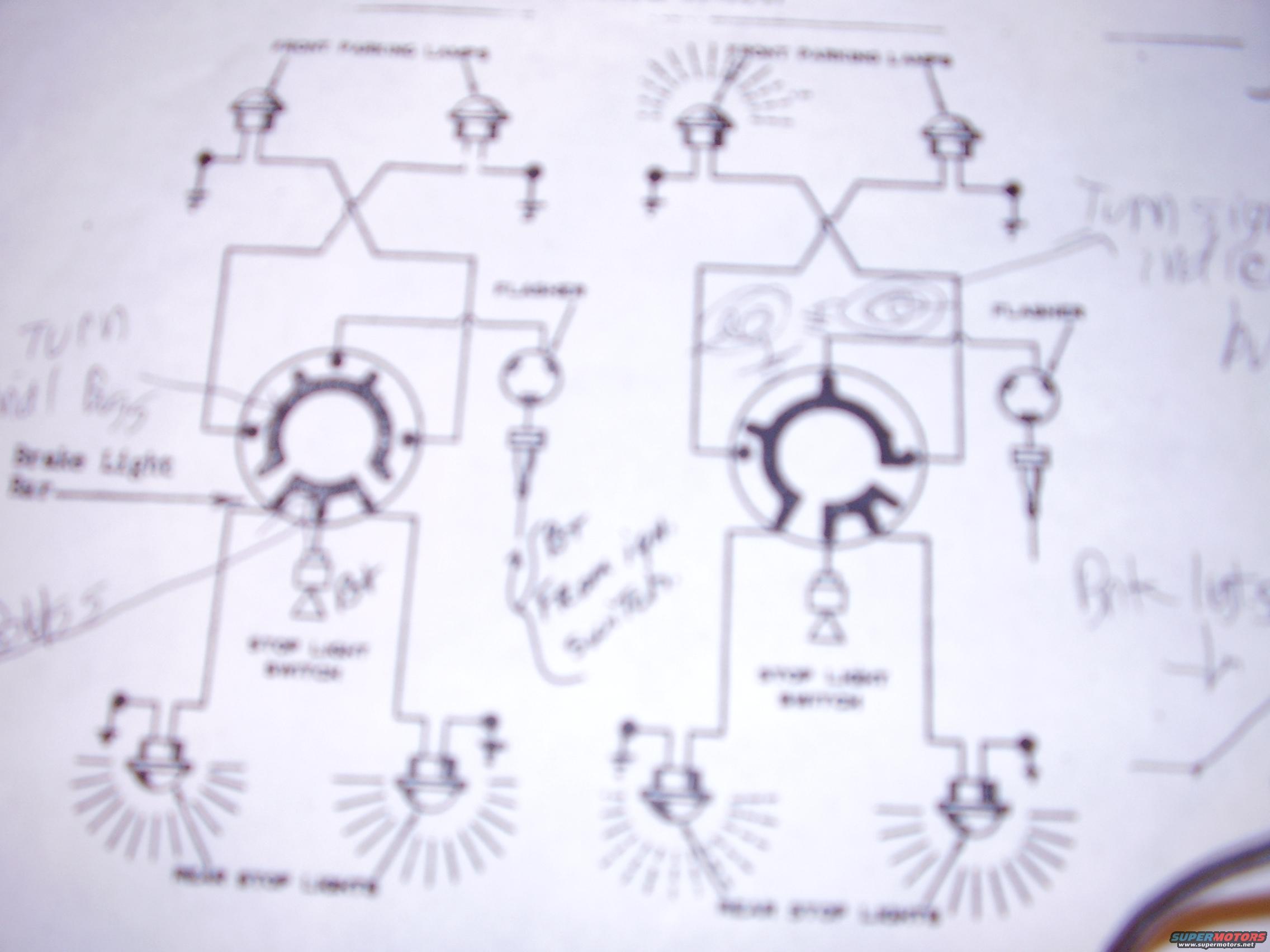
Wiring diagram of a turn-signal and stop-light system showing parking lights, flashers, turn-signal switch and stop-light switch.
Part of 1992-1996 Ford F-150 Wiring Diagrams
This document is a blurry photograph of a printed automotive wiring diagram page showing two side-by-side schematics of a turn signal / stop light circuit, apparently illustrating the circuit in two different operating states (one appears to show lamps illuminated, indicated by ray marks around bulbs). Each schematic shows two front parking lights wired through crossed conductors into a circular multi-contact turn signal switch, a flasher unit, a stop light switch, and two rear stop lights. Handwritten annotations by the owner identify components such as the turn signal bulbs, brake lights ('Brk lts'), a turn signal indicator, and what may be a lead to the ignition switch. The page appears to come from a service or training manual explaining how the turn signal switch routes current from the flasher and stop light switch to the front and rear lamps. No fuse ratings, wire colors, connector pin identifiers, part numbers, or vehicle year/model information are legible in the scan, so the exact vehicle application cannot be confirmed from the document itself. It was uploaded to a 1996 Ford F-150 gallery, but nothing visible confirms or contradicts that attribution.
Is this accurate? Sign in to help verify it.
Frequently asked questions
- What circuit does this wiring diagram show?
- It shows the turn signal and stop light circuit, including the front parking lights, flasher, turn signal switch, stop light switch, and rear stop lights.
- What components are labeled in the diagram?
- Printed labels include FRONT PARKING LIGHTS, FLASHER, STOP LIGHT SWITCH, and REAR STOP LIGHTS; handwritten notes point out the turn signal bulbs, brake lights, and turn signal indicator.
- Why are there two nearly identical diagrams on the page?
- The page shows the same turn signal/stop light circuit twice, apparently in two different operating states, in the right-hand diagram some lamps are drawn with illumination rays, suggesting it depicts the circuit with lamps energized.
- Does this diagram include fuse ratings or wire colors?
- No fuse ratings, wire colors, connector pins, or part numbers are legible anywhere on the page.
No comments yet.