Typical Turn Signal System Wiring Diagram - Flasher & Stop Light Switch Circuit

Reference · 1992-1996 F-150All 11 wiring diagrams
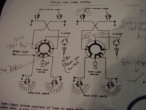
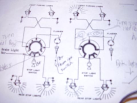
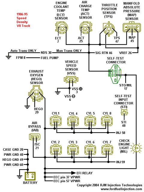
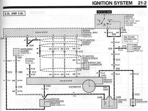

Typical turn-signal system wiring diagram showing front parking lights, flashers, stop-light switch and rear stop lights.
Part of 1992-1996 Ford F-150 Wiring Diagrams
This document is a scanned reference page titled "Typical Turn Signal Systems," showing two side-by-side schematic wiring diagrams of a generic automotive turn signal circuit. Each diagram depicts the front parking (turn signal) lights, a flasher unit, a rotary turn-signal switch with a brake light bar, the stop light switch, and the rear stop lights, with ground symbols and interconnecting wiring. The left diagram appears to show the circuit at rest; the right diagram shows the system in operation, with one front lamp and one rear lamp drawn illuminated (radiating lines) and turn-signal indicator bulbs sketched in. A previous owner has added handwritten study notes identifying the "turn signal bulbs," the "turn signal indicator bulb," a feed wire noted as coming from the ignition switch, and the brake light switch. A partially visible caption at the bottom begins to explain that a turn signal system consists of four or more bulbs, a flasher unit, and a stop lamp switch, but the rest is cut off. The page is a generic instructional/training diagram rather than a model-specific Ford wiring diagram; it contains no fuse ratings, wire color codes, part numbers, or year/model applicability. It was uploaded to a 1996 Ford F-150 gallery, likely as reference material for diagnosing turn signal or brake light wiring.
Is this accurate? Sign in to help verify it.
Frequently asked questions
- What components are shown in this typical turn signal system diagram?
- Front parking (turn signal) lights, a flasher unit, a turn signal switch with a brake light bar, the stop light switch, and the rear stop lights, all interconnected with wiring and grounds.
- How does the brake light circuit relate to the turn signal switch in this diagram?
- The stop light switch feeds through the turn signal switch, which contains a 'brake light bar' that routes brake current to the rear stop lights, and the same rear bulbs are used for the turn signals.
- Does this diagram show where the flasher gets its power?
- A handwritten note on the diagram indicates the feed wire to the flasher comes from the ignition switch.
- Is this diagram specific to a particular vehicle or year?
- No. It is labeled 'Typical Turn Signal Systems' and shows a generic circuit with no year, make, model, fuse ratings, wire colors, or part numbers.


No comments yet.