Home/
Registry/
Ford/
F-150/
1992-1996/
1994 Ford F-150/
Photo
supermotors.net/registry/media/814381
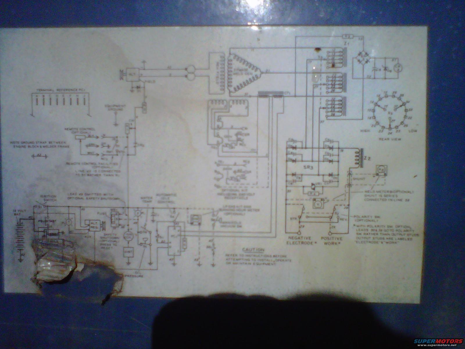
Engine-Driven Welder Generator Wiring Diagram Decal - Schematic Photo
Reference · 1992-1996 F-150All 11 wiring diagrams
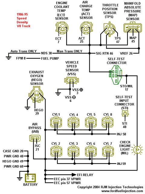
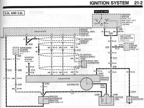
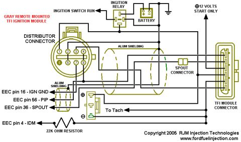
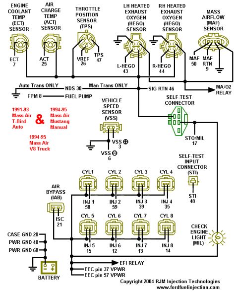
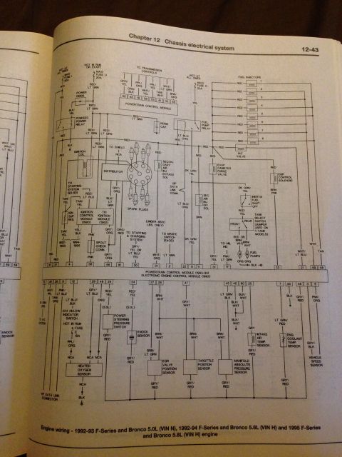
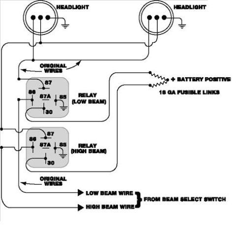
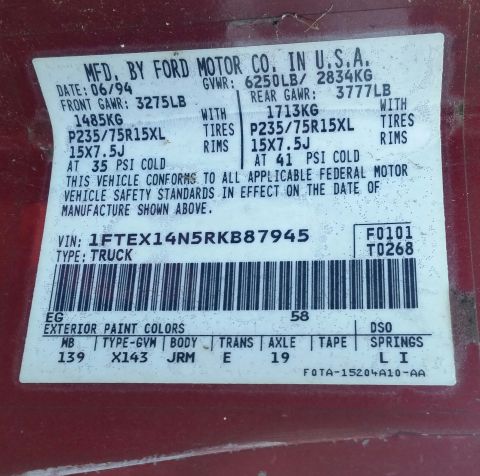

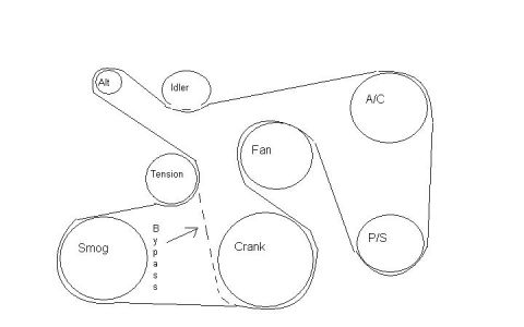
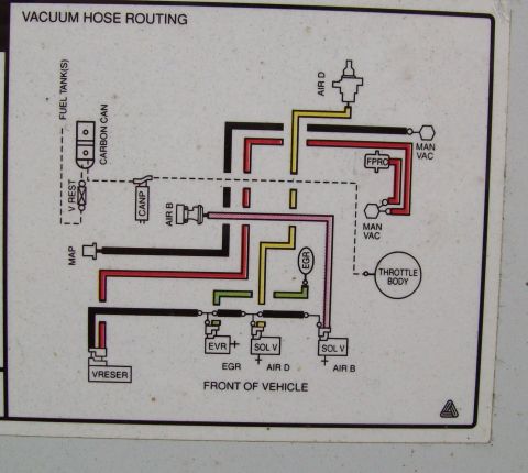
Photo of an electrical wiring schematic plate showing transformer, control circuitry, and positive/negative electrode terminal connections.
Part of 1992-1996 Ford F-150 Wiring Diagrams
This is a photograph of a wiring schematic decal from an engine-driven arc welder (welder/generator), showing the complete electrical circuit of the machine. The diagram includes the engine's 12-volt electrical system (12 volt battery, ignition switch, alternator with regulator, distributor, fuse, oil pressure and water temperature sensors, and an optional safety shutdown with press-to-reset), a 3-phase weld generator, rectifier assembly (SR3), reactors/transformers Z1 and Z2, and a multi-tap range switch (S3) shown in rear view with HIGH and LOW positions. Optional equipment documented includes a remote control, automatic idle control (with manifold vacuum switch), a weld meter with shunt series-connected in line 32, a 115V/240-volt receptacle kit with running hour meter, and a polarity switch, with a note that leads 30 & 39 go to the polarity switch rather than the output studs, which are labeled "ELECTRODE" and "WORK" (negative electrode, positive work). Notes call out a ground strap between engine block and welder frame, a terminal reference strip (PC1), and remote-control wiring changes (line 49 connected to 51). A caution advises referring to instructions before installing, operating, or maintaining the equipment. The image is dark and partially damaged, so many line numbers are unreadable.
Is this accurate? Sign in to help verify it.
Frequently asked questions
- What does this wiring diagram show?
- It is the schematic decal from an engine-driven welder, showing the 12-volt engine electrical circuit (battery, ignition switch, alternator and regulator, distributor, fuse), a 3-phase weld generator, rectifier SR3, reactors Z1 and Z2, a range tap switch (S3), and the welder output studs.
- How is the optional weld meter connected?
- Per the diagram note, the weld meter (optional) uses a shunt that is series connected in line 32.
- What happens to the wiring when the optional polarity switch is installed?
- The note states that with the polarity switch option, leads 30 & 39 go to the polarity switch rather than the output studs; the output studs are labeled "ELECTRODE" and "WORK" (negative electrode, positive work).
- Does the diagram mention any grounding requirement?
- Yes: a note calls for a ground strap between the engine block and the welder frame, and an equipment ground point is shown on the schematic.
- What optional accessories are shown on this welder schematic?
- Remote control, safety shutdown (press to reset), automatic idle control with manifold vacuum switch, a 115V kit with running hour meter, an optional kit including a 240-volt receptacle, a weld meter with shunt, and a polarity switch.






No comments yet.