Ford Bronco Dana 44 Front Disc Brake Exploded Diagram - Caliper, Rotor, Knuckle
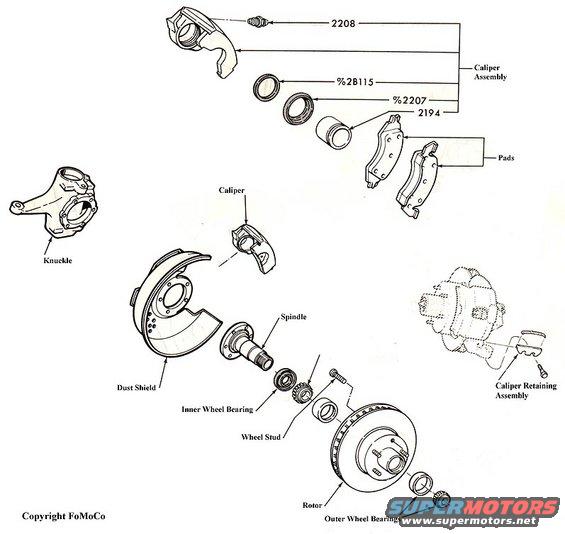
Exploded parts illustration of a front disc brake assembly with caliper, pads, rotor, spindle, wheel bearings and knuckle.
This is a Ford Motor Company (FoMoCo) exploded parts diagram showing a front disc brake and hub assembly, apparently for a Dana 44 front axle (per the uploader's filename). The illustration breaks the assembly into its major components: the caliper assembly (with internal parts identified by Ford basic part group numbers 2208, %2B115, %2207, and 2194, including seals and the caliper piston), the brake pads, the steering knuckle, the caliper housing, the dust shield, the spindle, the inner wheel bearing, a wheel stud, the rotor, the outer wheel bearings, and the caliper retaining assembly. Each part is drawn in exploded relationship to the others, showing assembly order along the spindle axis: knuckle, dust shield, spindle, inner bearing, rotor, and outer bearings, with the caliper and pads mounting over the rotor. A reader can learn the names of all major front disc brake components, their relative positions, and the order in which they stack during assembly or disassembly. No torque values, year/model applicability, or full service part numbers are given, only Ford basic group numbers for the caliper internals. The drawing carries a 'Copyright FoMoCo' notation, confirming it is an original Ford factory illustration.
Is this accurate? Sign in to help verify it.
Frequently asked questions
- What parts make up the caliper assembly in this diagram?
- The caliper assembly is shown exploded with components labeled by Ford group numbers 2208, %2B115, %2207, and 2194, which include the caliper housing, seals, and piston.
- What is the assembly order of the front hub and rotor components?
- Along the spindle axis the diagram shows the knuckle, dust shield, spindle, inner wheel bearing, wheel stud, rotor, and outer wheel bearings, with the caliper and pads mounting over the rotor.
- How is the caliper retained according to the diagram?
- A 'Caliper Retaining Assembly' is shown attaching to the knuckle/caliper mounting area with a key/spring piece and a retaining screw.
- Does the diagram show the brake pads?
- Yes, inner and outer brake pads are illustrated and labeled 'Pads' next to the caliper assembly.
Comments
More from this build






No comments yet.