Ford Non-Tilt Steering Column Exploded Diagram - Automatic, Shift Rod In Tube
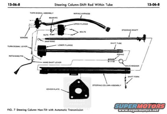
Exploded parts breakdown of a non-tilt steering column with automatic shift rod, labeling each component.
This document is a page (13-06-8) from a Ford factory shop manual section titled "Steering Column-Shift Rod Within Tube." It presents Figure 7, an exploded parts diagram of a non-tilt steering column used with an automatic transmission (column shift). The illustration shows the disassembled steering column with labeled components: the turn signal assembly, turn signal lever, wiring harness, bearing, upper and lower flanges with their bolts, nuts, and screws, a snap ring, the steering shaft, the shift tube, spring, wave washer, retaining pin, hand shift lever, shift fork, steering column assembly (outer tube), and cover plate. The figure reference code G2534-A appears at the lower right. A reader can learn how the column-shift steering column components are arranged and interrelate for disassembly or reassembly, for example, that the shift tube rides inside the column with a spring and wave washer, the hand shift lever is secured with a retaining pin, and the turn signal assembly mounts at the top with screws. No torque specifications, part numbers, or model-year applicability statements are printed on this page; it serves purely as a component identification/exploded-view reference for the non-tilt automatic-transmission steering column.
Is this accurate? Sign in to help verify it.
Frequently asked questions
- What does this diagram show?
- Figure 7 is an exploded parts view of a Ford non-tilt steering column used with an automatic transmission, from shop manual section 13-06-8 'Steering Column-Shift Rod Within Tube.'
- What parts are labeled in the steering column diagram?
- Turn signal assembly, turn signal lever, wiring harness, bearing, upper flange, lower flange, bolts, nuts, screws, snap ring, steering shaft, shift tube, spring, wave washer, retaining pin, hand shift lever, shift fork, steering column assembly, and cover plate.
- How is the hand shift lever attached to the column?
- The diagram shows the hand shift lever secured with a retaining pin.
- What components are associated with the shift tube?
- The shift tube is shown with a spring, a wave washer, and a shift fork, with the shift rod running within the column tube.
- Does this page give torque specs or part numbers?
- No. The page contains only the exploded illustration with component name callouts and the figure reference code G2534-A; no torque values or part numbers are shown.
Comments
More from this build






No comments yet.