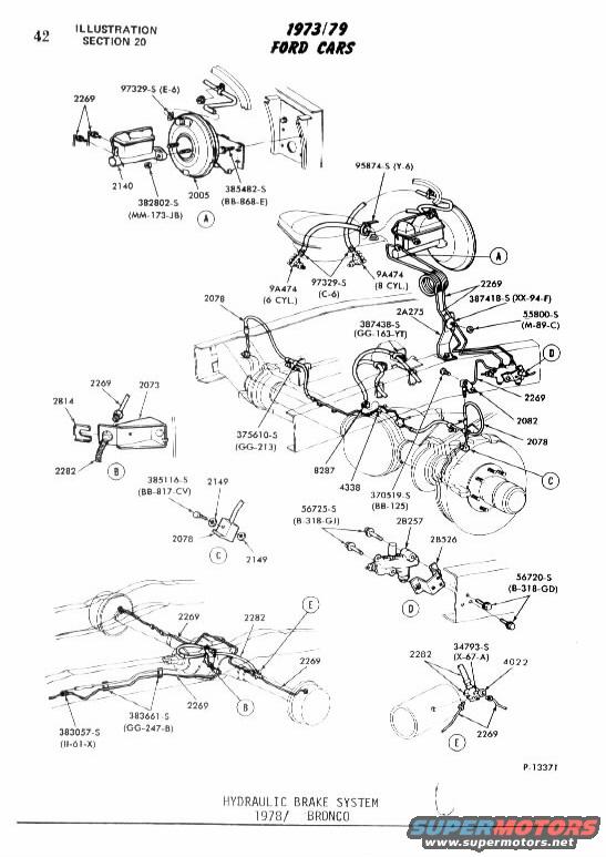
1978 Ford Bronco Hydraulic Brake System Exploded Diagram - Part Numbers
Reference · 1978-1979 BroncoAll 79 exploded parts diagrams


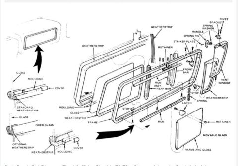
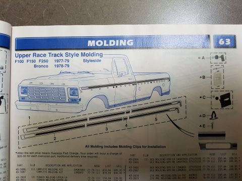
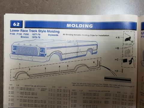



Exploded parts illustration of a hydraulic brake system showing booster, brake lines, valves and fittings with part numbers.
Part of 1978-1979 Ford Bronco Exploded Parts Diagrams
This is page 42 (Illustration Section 20) from a Ford parts illustration catalog covering 1973-79 Ford cars, showing the hydraulic brake system for the 1978 Bronco (illustration P-13371). The exploded parts diagram identifies the master cylinder (2140), brake booster (2005), brake lines and tubes (2269, 2282, 2A275, 2078, 2082), brackets (2073, 2814), pressure differential/proportioning valve components (28257, 28526), rear axle brake line routing, and related fittings. Detail views A through E show close-ups of the master cylinder/booster mounting (with variants noted for 6-cylinder and 8-cylinder engines via bolt 9A474), frame bracket attachments, junction blocks (2149), and rear axle line clips. Numerous hardware part numbers with Ford basic/suffix codes are called out, including 97329-S (E-6), 382802-S (MM-173-JB), 385482-S (BB-868-E), 95874-S (Y-6), 387418-S (XX-94-F), 55800-S (M-89-C), 387438-S (GG-163-YT), 375610-S (GG-213), 385116-S (BB-817-CV), 370519-S (BB-125), 56725-S (B-318-GJ), 56720-S (B-318-GD), 383661-S (GG-247-B), 383057-S (II-61-X), and 34793-S (X-67-A). The page is useful for identifying brake line routing, clip locations, and Ford part numbers when restoring or repairing a 1978 Bronco brake system.
Is this accurate? Sign in to help verify it.
Frequently asked questions
- What Ford part number is the master cylinder in the 1978 Bronco brake system diagram?
- The master cylinder is identified by basic part number 2140, mounted to the brake booster (2005) in detail view A.
- What part number covers the brake lines and tubes in this diagram?
- Brake lines/tubes are called out primarily as 2269 and 2282, with 2A275, 2078, and 2082 also labeled along the routing.
- Does the diagram differ for 6-cylinder and 8-cylinder engines?
- Yes, the booster mounting shows bolt 9A474 called out separately for 6 CYL. and 8 CYL. applications, with fastener 97329-S (C-6) nearby.
- What are the part numbers for the valve assembly shown in detail view D?
- View D shows valve components 28257 and 28526, with fasteners 56725-S (B-318-GJ) and 56720-S (B-318-GD).
- What years and model does this illustration apply to?
- The page header states 1973/79 Ford Cars, and the caption specifies the Hydraulic Brake System for the 1978 Bronco (illustration P-13371).






No comments yet.