Ford 400 CID (6.6L) Vacuum Diagram - Calibration 9-62M-R10, 10-5-78

Reference · 1978-1979 BroncoAll 16 vacuum routing diagrams
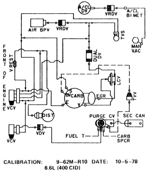

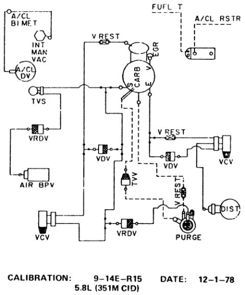
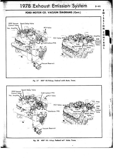
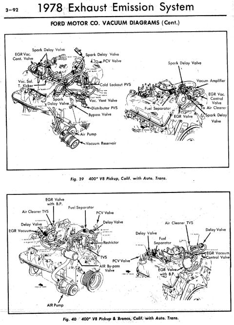
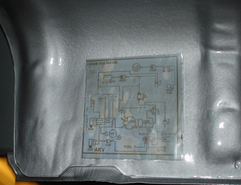
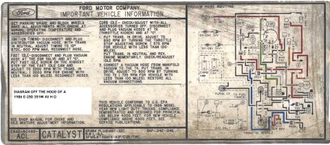
Vacuum hose routing diagram for a 6.6L 400 CID engine showing EGR, carburetor, distributor and emission valves with calibration label.
Part of 1978-1979 Ford Bronco Vacuum Routing Diagrams
This document is a factory emissions/vacuum hose routing schematic for a Ford 6.6L (400 CID) V8 engine, identified by calibration code 9-62M-R10 and dated 10-5-78. The diagram shows the vacuum hose connections between emission control components as viewed relative to the front of the engine. Components depicted include the air cleaner delay valve (A/CL DV), two vacuum retard delay valves (VRDV), air cleaner bi-metal sensor (A/CL BI MET), air bypass valve (AIR BPV), temperature vacuum switch (TVS), manifold vacuum source (MAN VAC), dual delay valve (DUAL DV), vacuum restrictor (V REST), two vacuum check/control valves (VCV), the carburetor with its S, B, E, and V vacuum ports, the EGR valve, load control valve (LCV), thermal vacuum valve (TVV), distributor (DIST), vacuum delay valve (VDV), purge control valve (PURGE CV), secondary canister (SEC CAN), fuel tank line (FUEL T), and carburetor spacer (CARB SPCR). A reader can use this diagram to correctly route or verify vacuum lines for the emissions and distributor advance systems on an engine bearing this specific calibration number.
Is this accurate? Sign in to help verify it.
Frequently asked questions
- What engine does this vacuum diagram cover?
- It covers the 6.6L (400 CID) engine, as stated at the bottom of the diagram.
- What calibration number applies to this vacuum routing diagram?
- Calibration 9-62M-R10, dated 10-5-78.
- What emission components are shown in this vacuum diagram?
- The diagram shows the A/CL DV, VRDV (two), A/CL BI MET, AIR BPV, TVS, MAN VAC source, DUAL DV, V REST, two VCVs, the carburetor (ports S, B, E, V), EGR valve, LCV, TVV, distributor (DIST), VDV, PURGE CV, SEC CAN, FUEL T line, and CARB SPCR.
- Which carburetor vacuum ports are identified in the diagram?
- The carburetor is shown with four labeled vacuum ports: S, B, E, and V.
- Where does the purge control valve connect in this system?
- The PURGE CV is shown connected to the SEC CAN (secondary canister), the FUEL T (fuel tank) line, and the CARB SPCR (carburetor spacer).






No comments yet.