1978 Ford Bronco 400 A/C Compressor Mounting Exploded Parts Diagram

Reference · 1978-1979 BroncoAll 79 exploded parts diagrams
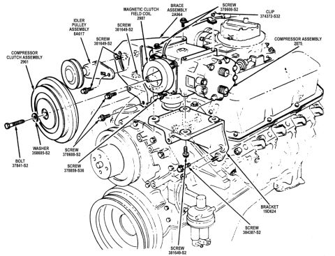

Exploded parts diagram of an air conditioning compressor and clutch assembly with idler pulley, brace and mounting hardware on a V8 engine.
Part of 1978-1979 Ford Bronco Exploded Parts Diagrams
This document is an exploded parts diagram showing the air conditioning compressor mounting arrangement on a Ford V8 engine (uploaded as applying to the 400 CID engine in a 1978 Ford Bronco). The line drawing depicts the front of the engine with the water pump pulleys and crankshaft pulley, and shows how the A/C compressor assembly (part 2875), compressor clutch assembly (2961), magnetic clutch field coil (2987), and idler pulley assembly (8A617) are assembled onto a mounting bracket (19D624) and brace assembly (2A964). Each fastener is called out with its Ford hardware part number, including bolt 37841-S2, washer 358605-S2, clip 374372-S32, and screws 381649-S2, 370608-S2, 378859-S36, and 384387-S2, with leader lines indicating exactly where each fastener installs on the engine and brackets. A reader can use this diagram to identify the correct Ford base part numbers for the compressor, clutch, field coil, idler pulley, bracket, and brace, and to see the assembly order and fastener locations when removing or reinstalling the A/C compressor and its mounting hardware. The diagram contains no torque specifications, year/model applicability text, or written instructions, only labeled callouts on the exploded illustration.
Is this accurate? Sign in to help verify it.
Frequently asked questions
- What is the Ford part number for the A/C compressor assembly in this diagram?
- The compressor assembly is labeled with part number 2875.
- What part number is the compressor clutch assembly?
- The compressor clutch assembly is part number 2961, and the magnetic clutch field coil is 2987.
- What bracket holds the A/C compressor on this engine?
- The diagram shows bracket 19D624 along with brace assembly 2A964 supporting the compressor.
- What fastener part numbers are used to mount the compressor and idler pulley?
- The diagram calls out bolt 37841-S2, washer 358605-S2, clip 374372-S32, and screws 381649-S2, 370608-S2, 378859-S36, and 384387-S2.
- What is the idler pulley assembly part number?
- The idler pulley assembly is part number 8A617.
No comments yet.