SuperMotors SuperMotors SUPERMOTORS Search: try “orange Bronco on 35s”
Home/ Registry/ Ford/ Bronco/ 1978-1979/ “Lula Mae”/ Photo supermotors.net/registry/media/307014

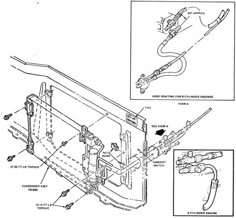
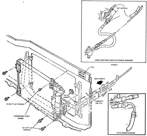
Ford Bronco A/C Condenser Mounting & Hose Routing Diagram (19C600) - 6 & 8 Cyl

Ford A/C condenser assembly and ambient switch vacuum hose routing diagram
Ford A/C condenser assembly and ambient switch vacuum hose routing diagramOriginal file
Ford A/C condenser assembly and ambient switch vacuum hose routing diagram

Reference · 1978-1979 BroncoAll 16 vacuum routing diagrams
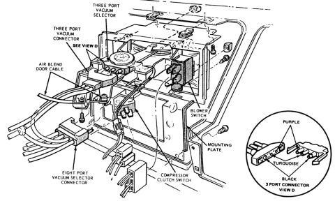
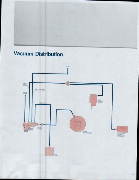
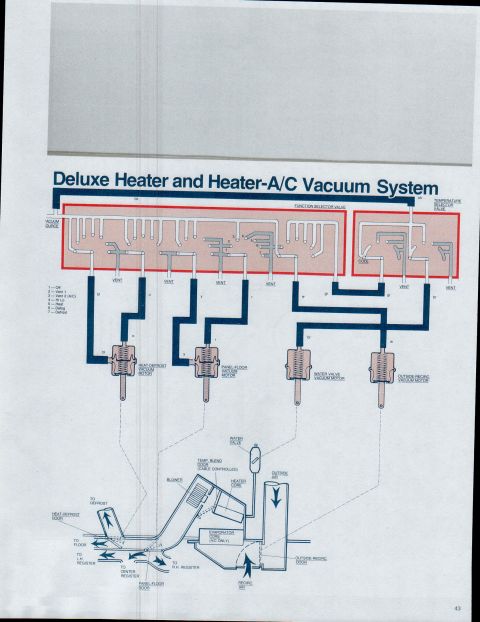
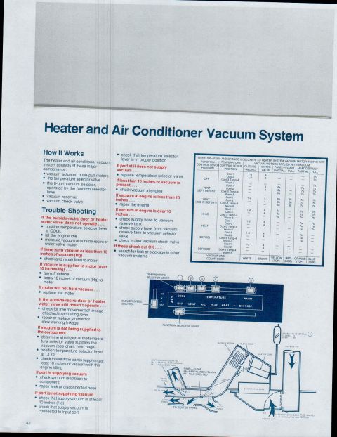
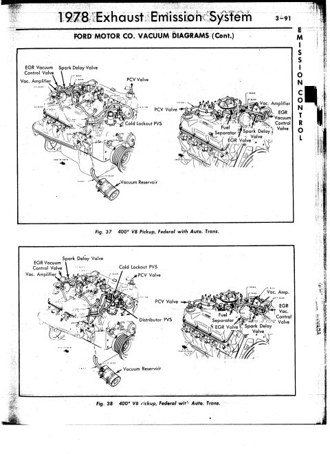
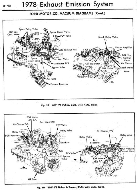
Ford 400 CID (6.6L) Vacuum Diagram - Calibration 9-62M-R10, 10-5-78 1978 Ford Bronco Heater & A/C Control Assembly Diagram - Vacuum Connectors Ford Bronco A/C Condenser Mounting & Hose Routing Diagram (19C600) - 6 & 8 Cyl Ford Bronco A/C Condenser Assembly 19C600 Installation & Hose Routing Diagram 1979 Ford Bronco & F100-F350 Vacuum Distribution Diagram - Hose Routing 1979 Ford Bronco/F100-F350 Deluxe Heater & Heater-A/C Vacuum System Diagram 1978-79 Ford F100-F350 Bronco Heater/AC Vacuum System Diagram & Test Chart 1978 Ford 400 V8 Pickup Vacuum Diagram - Federal Auto Trans (Figs 37-38) 1978 Ford 400 V8 Vacuum Diagram - Pickup & Bronco California Auto Trans 1978 Ford Bronco Hand-Drawn Vacuum Routing Diagram - Engage/Disengage Valves 5.8L 351M vacuum hose routing diagram, calibration 9-14E-R15, with CARB, EGR, TVS, VDV and VRDV Vacuum hose routing decal with VRDV, EGR, AKV, purge CV and carburetor connections 16vacuum routing diagrams1978-1979 Ford Bronco More reference 1979 Ford Pickup Brochure Page 19 - F-100/F-150 Options, Wheels & Tu-Tone PaintBrochure 1978 Ford Bronco Tailgate Latch Release Mechanism Exploded DiagramExploded parts Dana 60 Axle ID Diagram - Bill of Material, Date Code, Model Number & Ratio TagSpec plate Engine weight comparison chart listing engines by make with weight in pounds and notesManual page Ford Bronco A/C Register & Louver Removal Diagram - Dash Vent ProcedureService procedure Piston Engine Cycle Animation Diagram - Single Cylinder Cross-SectionSchematic Bolt identification guide chart of head markings, grades, materials and tensile strengthsTorque spec Ford Bronco Wiring Diagram - Ignition, Wiper Motor & Back-Up Light CircuitsWiring diagram 1978 Ford Bronco Custom Bumper Build - SolidWorks CAD Assembly ScreenshotBlueprint 1979 Ford Bronco & F100-F350 Fuse Block Diagram - Fuse Positions & Amp RatingsFuse chart

A/C condenser assembly (19C600) exploded view with mounting torque specs plus vacuum/ambient-switch hose routing for 8-cylinder and 6-cylinder engines (View A). Duplicate of media 306845.

Part of 1978-1979 Ford Bronco Vacuum Routing Diagrams

AI caption · Photo 305 of 526

This document is a scanned exploded-view illustration of an air conditioning condenser assembly installation, apparently from a Ford factory service manual. The main drawing shows the A/C condenser assembly (part reference 19C600) mounted to the radiator support/front panel, with mounting screws called out at two torque specifications: 21-55 ft-lb for the larger fasteners and 10-14 ft-lb for the smaller screws. Additional callouts identify a nut (45264), the ambient switch located on the panel, and an "Air Conditioning" identification tag. Refrigerant hose and receiver-drier plumbing is shown attached to the condenser. An upper inset labeled "View A" details the hose routing for 8-cylinder engines, noting a fitting angle of approximately 45 degrees, while a lower-right inset shows the differing hose/fitting arrangement for the 6-cylinder engine. A reader can learn how the condenser mounts to the vehicle, the correct fastener torque values, where the ambient switch is located, and how the A/C hoses route differently between 6-cylinder and 8-cylinder engine applications.

Is this accurate? Sign in to help verify it.

Frequently asked questions

What torque is used on the A/C condenser mounting fasteners?
The diagram calls out two torque specs: 21-55 ft-lb for the larger mounting fasteners and 10-14 ft-lb for the smaller screws.
What is the part reference for the condenser assembly?
The condenser assembly is labeled 19C600 in the diagram.
Is the A/C hose routing different for 6-cylinder and 8-cylinder engines?
Yes. View A shows hose routing for 8-cylinder engines (with a fitting angle of approximately 45°), and a separate inset shows the routing for the 6-cylinder engine.
Where is the ambient switch located?
The diagram shows the ambient switch mounted on the radiator support panel near the condenser, secured with nut 45264.


Comments

No comments yet.

More 1978-1979 Broncos