Ford Truck & Bronco Door Latch, Lock & Handle Exploded Parts Diagram

Reference · 1978-1979 BroncoAll 79 exploded parts diagrams


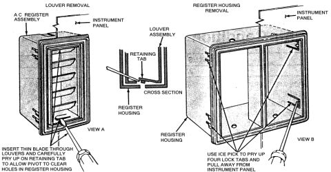




Exploded parts diagrams of door latch, lock set, inside and outside handles, rods, clips and remote control linkage components.
Part of 1978-1979 Ford Bronco Exploded Parts Diagrams
This scanned page is an exploded parts diagram set covering Ford door latch, lock, and handle components, apparently from a factory shop manual or parts catalog. It contains three main figures plus several detail views. Figure 1 shows the interior door latch mechanism with rod 21852, latch 21812-3, link 21914, rod 22134, remote control 21818, handle 22614, and associated clips and screws (Views A and B). Figure 3 shows the door lock system, including lock knob 21850, rod 21852, latch assembly 21812-3, and screw 356782. A right-hand panel details the exterior door handle 22400-1 with nut 45332, bushing 219A38, clip 21952, and rod 22152; another panel shows the lock set with clip, bushing, and retainer. A lower-left blow-up (View B) shows the inside handle 22614 and remote control 21818 with screw-and-washer 57030, U-nut 45263, and screw 57546. Figure 2 shows the door striker 21982 and shim 22058. Two lower-right panels distinguish latch installation views for F-100-350 and F-500-750 truck series. The diagram helps identify part group numbers and the physical relationship of door latch hardware for disassembly, repair, or parts ordering.
Is this accurate? Sign in to help verify it.
Frequently asked questions
- What part number is the door latch assembly in this diagram?
- The latch assembly is labeled 21812-3, shown in both Figure 1 and Figure 3, attached with screw 356782 in Figure 3.
- What parts make up the exterior door handle assembly?
- The exterior handle is part 22400-1, secured with nut 45332, and connects via rod 22152 with bushing 219A38 and clip 21952.
- What is the part number for the interior door handle and remote control?
- The interior handle is 22614 and the remote control is 21818, mounted with screw and washer 57030, U-nut 45263, and screw 57546, linked by link 21914.
- What parts are shown for the door striker?
- Figure 2 shows striker 21982 with shim 22058.
- Does this diagram cover different Ford truck series?
- Yes, separate latch views are shown for F-100-350 and F-500-750 series trucks.






No comments yet.