Ford NP205 Transfer Case Installation & Linkage Exploded Diagram (7A195)

Reference · 1978-1979 BroncoAll 79 exploded parts diagrams
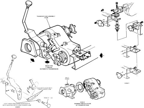
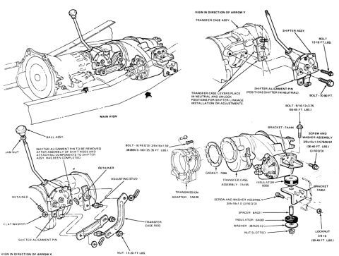
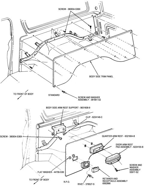
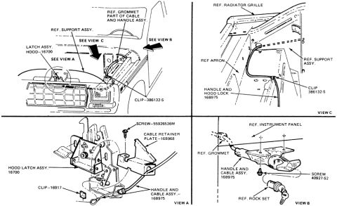
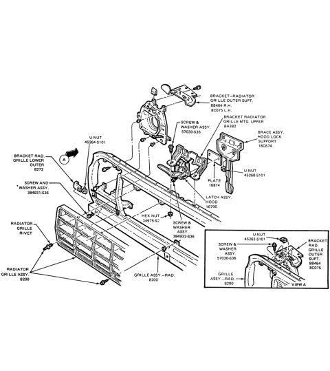

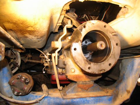
Exploded parts breakdown of the transfer case assembly showing shifter linkage and mounting bracket installation views.
Part of 1978-1979 Ford Bronco Exploded Parts Diagrams
This is a Ford factory-style exploded parts illustration showing the transfer case assembly (Ford base part number 7A195) and its installation. The main view depicts the transfer case with attached shift lever and linkage as installed in an F-100 (4x4) with automatic transmission, with directional arrows indicating three detail views (X, Y, and Z). View X shows the installation of the transfer case itself, split apart from its adapter/mounting housing, and calls out bolt part number 383890. View Y is an exploded view of the transfer case mounting brackets, crossmember hardware, insulators/bushings, and fasteners. View Z details the shift lever and linkage assembly, with service notes instructing the mechanic to coat both ends of the linkage rod with Ford Chassis Lube, to coat the inner and outer surfaces of both bushings with Ford Chassis Lube, and specifying a torque of 70-90 ft.-lb. for a fastener in the shift linkage. A reader can learn the component arrangement, mounting hardware layout, one torque specification, lubrication points, and two part numbers (7A195 transfer case assembly, 383890 bolt) for servicing or reassembling this transfer case installation.
Is this accurate? Sign in to help verify it.
Frequently asked questions
- What is the Ford base part number for the transfer case assembly shown?
- The transfer case assembly is identified as part number 7A195.
- What torque spec is given for the shift linkage fastener?
- The diagram specifies 70-90 ft.-lb. in View Z of the shift lever/linkage detail.
- Where should Ford Chassis Lube be applied on the shift linkage?
- Coat both ends of the linkage rod with Ford Chassis Lube, and coat the inner and outer surfaces of both bushings with Ford Chassis Lube.
- What bolt part number is called out for the transfer case installation?
- Bolt part number 383890 is called out in View X, which shows the installation of the transfer case.
- What vehicle configuration does the main view depict?
- The main view is labeled for an F-100 (4x4) with automatic transmission.
No comments yet.