Ford Bronco & F-150 4x4 Power Steering Pump Installation Diagram - 300/351/400

Reference · 1978-1979 BroncoAll 79 exploded parts diagrams


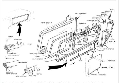
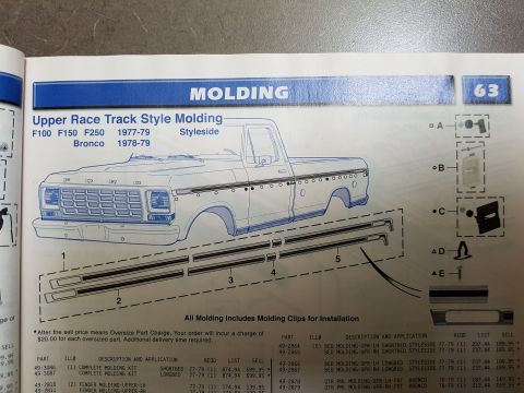
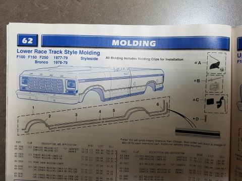
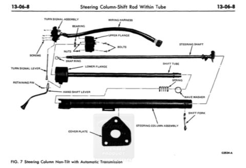



Exploded parts breakdown of power steering pump installation across several engines, showing support brackets, pulley and pressure/return hoses.
Part of 1978-1979 Ford Bronco Exploded Parts Diagrams
This document is an exploded-view illustration showing typical power steering pump installations on Ford Bronco and F-150 (4x4) trucks. It contains three related views. The upper-left view, labeled "View in direction of X," shows the typical power steering pump installation with the 4.9L (300 CID) inline-6 engine, calling out the pump support, adjusting bracket, and pulley. The center-right "main view for Bronco and F-150 (4x4)" shows the power steering pump mounted at the engine with its drive belt routing, and identifies the pressure hose and return hose running along the frame to the steering gear. The lower-left view, labeled "View in direction of arrow X," shows the typical power steering pump installation for the 5.8L (351 CID) V-8 or 6.6L (400 CID) V-8 engines, calling out the frame side member, pump support, and pulley. A note specifies that the pulley, with its pull-off groove facing front, is to be pressed on flush with the end of the shaft ±.010. A reader can learn how the power steering pump, brackets, hoses, and pulley are arranged and mounted for each engine option.
Is this accurate? Sign in to help verify it.
Frequently asked questions
- Which engines does this power steering pump installation diagram cover?
- It shows typical power steering pump installations for the 4.9L (300 CID) I-6 engine and for the 5.8L (351 CID) V-8 or 6.6L (400 CID) V-8 engines.
- Which vehicles does the main view apply to?
- The main view is labeled for the Bronco and F-150 (4x4).
- How should the power steering pump pulley be installed?
- The pulley, with the pull-off groove facing front, is to be pressed on flush with the end of the shaft ±.010.
- What hoses are identified on the power steering system?
- The diagram labels the pressure hose and the return hose running from the power steering pump to the steering gear.
- What mounting components are shown for the V-8 pump installation?
- The V-8 installation view calls out the frame side member, pump support, and pulley along with the attaching bolts.






No comments yet.