1978 Ford Bronco Front Suspension Exploded Diagram - Torque Specs & Views

Reference · 1978-1979 BroncoAll 79 exploded parts diagrams
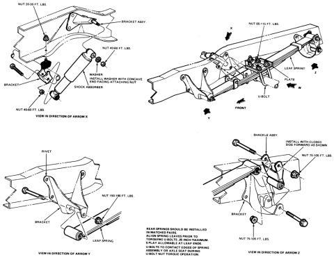
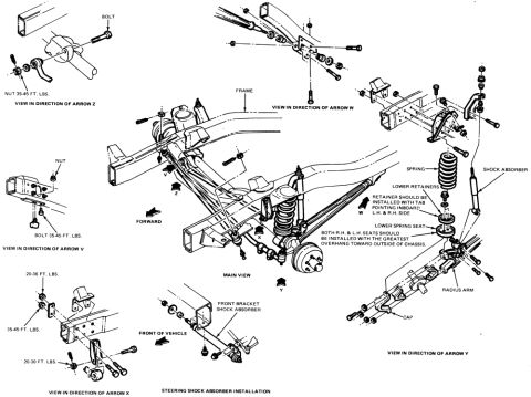
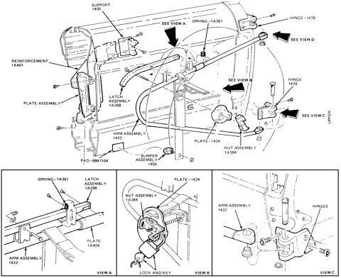
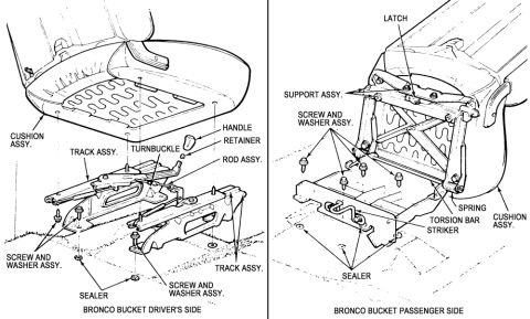
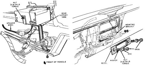
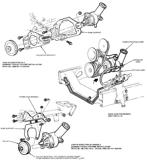
Exploded parts breakdown of the front suspension showing springs, shock absorbers, radius arms and brackets with torque specifications.
Part of 1978-1979 Ford Bronco Exploded Parts Diagrams
This document is an exploded parts diagram of a front suspension assembly, uploaded to accompany a 1978 Ford Bronco. The illustration centers on a main view of the frame and front axle area, with directional arrows (V, W, X, Y, Z) pointing to detailed inset views around the perimeter. The insets show fastener orientation and torque specifications: View Z shows a bolt and nut torqued to 35-45 ft. lbs.; View V shows a nut and a bolt at 35-45 ft. lbs.; View X shows fasteners at 20-36 ft. lbs., 35-45 ft. lbs., and 20-30 ft. lbs. View W shows a bracket assembly at the frame. View Y details the coil spring, shock absorber, lower retainers, lower spring seat, radius arm, and cap, with installation notes stating the retainer should be installed with the tab pointing inboard on both left- and right-hand sides, and that both spring seats should be installed with the greatest overhang toward the outside of the chassis. A separate lower detail shows the steering shock absorber installation with its front bracket relative to the front of the vehicle. The document contains no part numbers, year, or model text.
Is this accurate? Sign in to help verify it.
Frequently asked questions
- What are the torque specs shown for the front suspension fasteners?
- View Z: nut 35-45 ft. lbs.; View V: bolt 35-45 ft. lbs.; View X: fasteners at 20-36 ft. lbs., 35-45 ft. lbs., and 20-30 ft. lbs.
- How should the lower spring retainer be installed?
- The retainer should be installed with the tab pointing inboard, on both the left-hand and right-hand sides.
- How are the lower spring seats oriented?
- Both right-hand and left-hand seats should be installed with the greatest overhang toward the outside of the chassis.
- Does the diagram cover the steering shock absorber?
- Yes, a separate detail labeled 'Steering Shock Absorber Installation' shows the front bracket and its mounting relative to the front of the vehicle.
- What suspension components are labeled in View Y?
- Spring, shock absorber, lower retainers, lower spring seat, radius arm, and cap.
No comments yet.