Ford 351/400 Breakerless Ignition Wiring Diagram - Duraspark & Dual Battery Relay

Reference · 1978-1979 BroncoAll 116 wiring diagrams
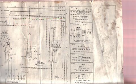
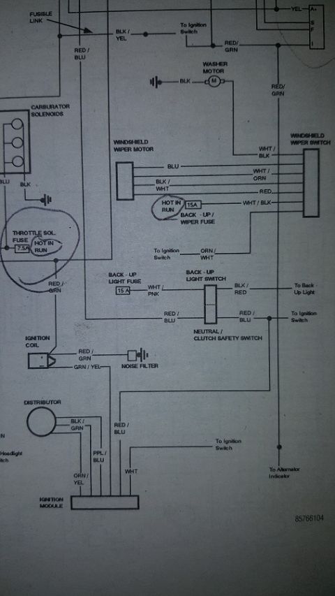
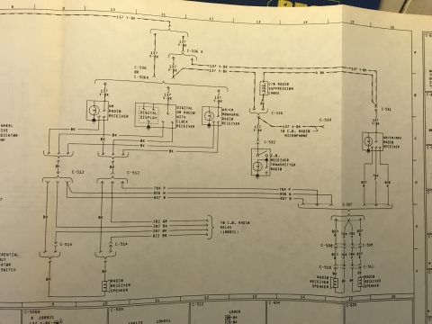
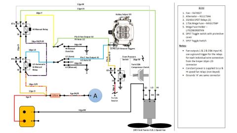
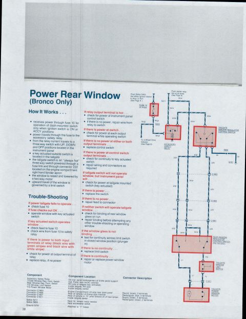
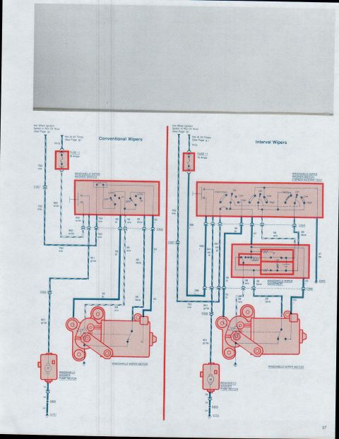

Wiring diagram for a breakerless ignition system showing distributor, ignition coil, switches and color-coded circuits.
Part of 1978-1979 Ford Bronco Wiring Diagrams
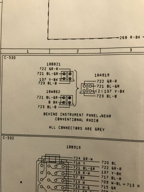
This is one page of a factory-style Ford wiring diagram covering the ignition and starting-related circuits for an 8-cylinder 351/400 engine with a breakerless (Duraspark-type) distributor. The schematic shows the breakerless distributor, breakerless ignition modulator, ignition coil (with a resistance wire noted as 1.05 to 1.15 ohms), a fuse link (526 BK-W), radio ignition interference capacitor, and the transmission gear shift neutral switch. Wire circuits are identified by number and color code, including 16 R-GR, 32 R-BL, 37 BK-Y, 526 BK-W, 297 BK-GR, 232 GR-Y, 732 W, 733 BK-GR, 734 O-Y, 735 P-BL, 904 GR-R, 138 W-P, 140 BK-R, 262 BR, and 198 BK. A right-hand legend column details connector locations and part numbers: C-323 (14289, breakerless ignition module on the L.H. fender apron), C-1015 (7E203/14401, backup lamp switch on the transmission housing), C-1201/C-1202 (14300/14301, auxiliary battery positive and negative terminals), and C-1203/C-1205 (14300/14A303, dual battery relay on the L.H. fender apron, aft). A reader can trace ignition circuit wiring, identify connector locations, and match wire colors/circuit numbers for troubleshooting.
Is this accurate? Sign in to help verify it.
Frequently asked questions
- Where is the breakerless ignition module (connector C-323) located?
- In the engine compartment, on the L.H. fender apron; connector C-323 (part 14289) is part of the breakerless ignition module.
- What resistance is specified for the ignition resistance wire?
- The diagram notes 1.05 to 1.15 ohms in the 16 R-GR circuit feeding the ignition coil.
- Where is the backup lamp switch located and what connector serves it?
- Connector C-1015 (7E203 / 14401), located on the transmission housing, serves the backup lamp switch, using wires 32 R-BL, 138 W-P, and 140 BK-R in a gray connector.
- Where are the dual battery relay connectors located?
- Connectors C-1203 (14300) and C-1205 (14A303) are on the L.H. fender apron, aft, at the dual battery relay. C-1205 carries wires 297 BK-GR and 198 BK.
- What connectors go to the auxiliary battery?
- C-1201 (14300, red wire) at the positive terminal and C-1202 (14301, black wire) at the negative terminal, both forward on the L.H. fender apron.





No comments yet.