Home/
Registry/
Ford/
Bronco/
1978-1979/
“Black Betty”/
Photo
supermotors.net/registry/media/1107279
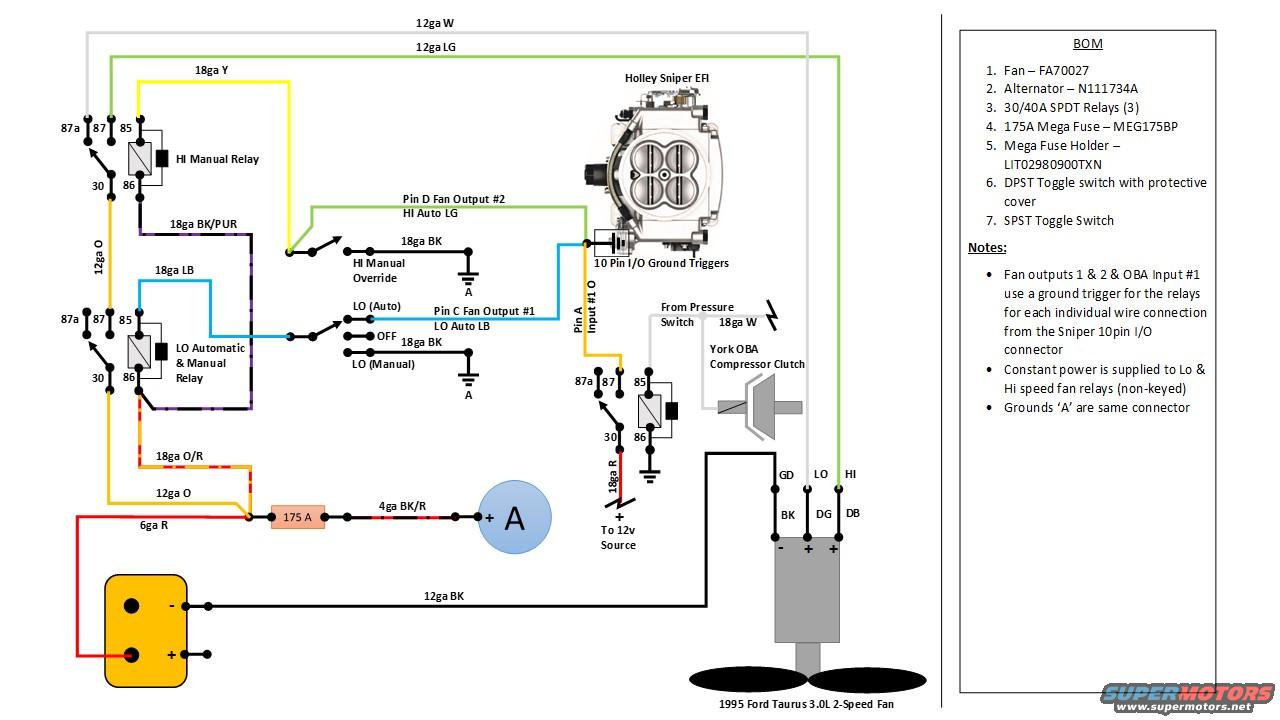
2-Speed Taurus Electric Fan Wiring Diagram - Holley Sniper EFI Relay Schematic
Reference · 1978-1979 BroncoAll 116 wiring diagrams


Custom electric fan control wiring diagram for a 1995 Taurus 3.0L 2-speed setup using Holley Sniper EFI fan outputs, SPDT relays, a 175A MegaFuse and toggle switches.
Part of 1978-1979 Ford Bronco Wiring Diagrams
This is a custom wiring schematic (V2) for installing a 1995 Ford Taurus 3.0L two-speed electric cooling fan controlled by a Holley Sniper EFI system's 10-pin I/O ground-trigger outputs. The diagram shows three 30/40A SPDT relays: a HI manual relay, a LO automatic & manual relay, and a relay for a York OBA (onboard air) compressor clutch triggered by a pressure switch. Fan Output #1 (Pin C, light blue wire) drives the LO speed, Fan Output #2 (Pin D, light green wire) drives the HI speed, and Input #1 (Pin A, orange wire) connects to the OBA circuit. Manual override toggle switches (HI manual override and a LO Auto/OFF/LO Manual switch) ground the relay coils through common ground 'A'. Power flows from the battery through a 6ga red wire, a 175A Mega fuse, and 4ga BK/R wire to the alternator, with 12ga orange feeding constant (non-keyed) power to both fan relays. Wire gauges and colors are labeled throughout (12ga W, 12ga LG, 18ga Y, 18ga BK/PUR, 18ga LB, 18ga BK, 18ga O/R, 18ga R, 12ga BK). A bill of materials lists the fan (FA70027), alternator (N111734A), relays, 175A Mega fuse (MEG175BP), fuse holder (LIT02980900TXN), and DPST/SPST toggle switches. Fan connector pinout: GD/LO/HI with BK/DG/DB wires.
Is this accurate? Sign in to help verify it.
Frequently asked questions
- What fan is used in this two-speed electric fan wiring schematic?
- A 1995 Ford Taurus 3.0L 2-speed fan, listed in the BOM as part FA70027, with a connector pinout of GD (BK wire), LO (DG wire), and HI (DB wire).
- Which Holley Sniper EFI pins control the fan speeds?
- Pin D (Fan Output #2, HI, light green wire) controls high speed, Pin C (Fan Output #1, LO, light blue wire) controls low speed, and Pin A (Input #1, orange wire) is used for the OBA circuit. All are ground triggers from the Sniper 10-pin I/O connector.
- What size fuse protects the main power feed?
- A 175A Mega Fuse (part MEG175BP) in a Mega Fuse Holder (LIT02980900TXN), placed between the 6ga red battery wire and the 4ga BK/R wire to the alternator.
- How are the fan relays powered?
- Constant (non-keyed) power is supplied to both the LO and HI speed fan relays, per the notes on the diagram.
- What relays are specified in the bill of materials?
- Three 30/40A SPDT relays: a HI manual relay, a LO automatic & manual relay, and one for the York OBA compressor clutch.






No comments yet.