Home/
Registry/
Ford/
LTD Crown Victoria/
1983-1991/
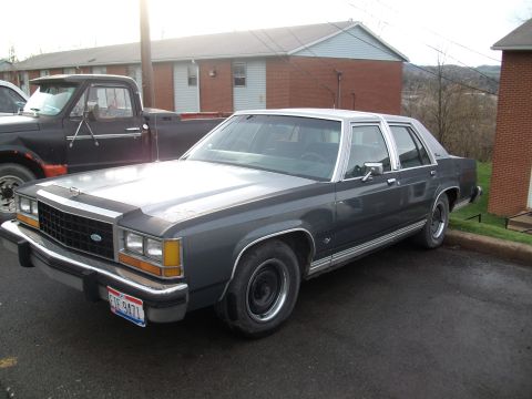
1985 Ford LTD Crown Victoria/
Photo
supermotors.net/registry/media/504713
1987 Ford LTD Crown Victoria 5.0L Vacuum Diagram - Calibrations 7-22/7-23

5.0L 1987 Crown Victoria emission vacuum routing showing FPR, manifold-vacuum solenoid valves and EGR/ACV plumbing for multiple calibrations.
Part of 1983-1991 Ford LTD Crown Victoria Vacuum Routing Diagrams
This document is a scanned vacuum routing diagram (Fig. 4) from Mitchell Repair Information Company (© 2003), credited as courtesy of Ford Motor Co., for the 1987 Ford LTD Crown Victoria with the 5.0L engine. It applies to a specific set of engine calibrations: 7-22B-R00, 7-22E-R00, 7-22E-R10, 7-22G-R00, 7-22H-R00, 7-22H-R10, 7-22I-R00, 7-22J-R00, 7-22Q-R00, 7-22S-R00, 7-23B-R00, 7-23C-R00, and 7-23R-R00. The schematic shows vacuum hose routing among emissions and engine-control components, identified by abbreviations: MAP sensor, PCV valve, vacuum reservoir (VRESER), fuel pressure regulator (FPR), vacuum check valve (VCKV), EVR, air control valve (ACV), two solenoid valves (SOL V), air bypass valve (ABV), four manifold vacuum (MAN VAC) taps, EGR valve, air pump, CPRV, vacuum restrictor (V-REST), fuel tank line, and charcoal canister (CAN). Solid lines indicate vacuum hoses and dashed lines indicate reference/other connections, with orientation noted as "FRONT OF VEHICLE." A reader can use this diagram to verify or restore correct vacuum hose routing on a matching 5.0L calibration, useful when diagnosing emissions, EGR, air injection, or evaporative system problems. Figure ID number 200742 appears on the diagram; the page was printed February 13, 2004.
This document covers 1987, which may differ from this 1985 Ford LTD Crown Victoria.
Is this accurate? Sign in to help verify it.
Frequently asked questions
- What vehicle and engine does this vacuum diagram cover?
- It is labeled for the 1987 Ford LTD Crown Victoria with the 5.0L engine.
- Which engine calibrations does this vacuum diagram apply to?
- Calibrations 7-22B-R00, 7-22E-R00, 7-22E-R10, 7-22G-R00, 7-22H-R00, 7-22H-R10, 7-22I-R00, 7-22J-R00, 7-22Q-R00, 7-22S-R00, 7-23B-R00, 7-23C-R00, and 7-23R-R00.
- What components are shown in the diagram?
- MAP, PCV, VRESER (vacuum reservoir), FPR, VCKV, EVR, ACV, two SOL V solenoid valves, ABV, four MAN VAC (manifold vacuum) taps, EGR, AIR PUMP, CPRV, V-REST, FUEL TANK, and CAN (canister).
- What is the source of this diagram?
- It is Fig. 4 from Mitchell Repair Information Company (© 2003), courtesy of Ford Motor Co., printed Friday, February 13, 2004.
- How is the diagram oriented?
- The bottom of the diagram is labeled 'FRONT OF VEHICLE'.
Comments
More from this build








No comments yet.