Home/
Registry/
Ford/
LTD Crown Victoria/
1983-1991/
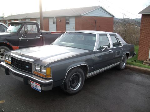
1985 Ford LTD Crown Victoria/
Photo
supermotors.net/registry/media/504733
1984-87 Ford ATC Vacuum Diagram - Grand Marquis, Town Car, Crown Victoria

1984-87 automatic temperature control vacuum routing showing mode-door vacuum motors, check valve, vacuum tank and floor/defrost/panel door circuits.
Part of 1983-1991 Ford LTD Crown Victoria Vacuum Routing Diagrams
This document is a scanned page from Mitchell Repair Information (© 2003) showing Fig. 8: the 1984-87 Automatic Temperature Control (ATC) vacuum diagram for the Ford/Mercury Grand Marquis and Lincoln Town Car, filed under a 1987 Ford LTD Crown Victoria heading in the A/C-Heater System - Automatic section. The diagram traces vacuum hose routing from the vacuum tank through a check valve and dash panel grommet to the ATC valve assembly (D9AH-19C988), servo diverter, AFC sensor, TBL switch, and vacuum motors controlling the temperature blend door, floor, defrost, partial panel, full panel, recirc air, and ambient air door positions. Hose colors are identified along the routing (black source, orange, red, yellow, white, blue, purple, turquoise), and harness assemblies D9AH-19C827 and D9AH-19C988 are called out. A function lever position table maps each of the eight valve ports (recirc, partial panel, full floor, source, servo divert, EVR, partial floor, full panel) to its state (vacuum, atmosphere, or sealed) in each control setting: OFF, VENT, A/C, HI-LO, FLOOR, MIX, and DEF, along with each port's hose color. A legend defines V = vacuum, A = atmosphere, NV = no vacuum. This allows diagnosis of ATC vacuum faults by mode and hose color.
Is this accurate? Sign in to help verify it.
Frequently asked questions
- What hose color is the vacuum source on the 1984-87 ATC system?
- The source (port 4) uses the black hose, and it has vacuum in all function lever positions (OFF, VENT, A/C, HI-LO, FLOOR, MIX, DEF).
- Which port and hose color controls the recirculating air door?
- Port 1 (RECIR-FA) uses the white hose. It sees vacuum in OFF, atmosphere in VENT, HI-LO, MIX and DEF, connects to port 5 in A/C, and to port 6 in FLOOR.
- What do the abbreviations V, A, and NV mean in this diagram?
- Per the legend: V = vacuum, A = atmosphere, NV = no vacuum.
- What part numbers are shown for the ATC vacuum components?
- The diagram calls out harness assemblies D9AH-19C827 and D9AH-19C988, and the ATC valve assembly D9AH-19C988 (plan view).
- Which hose operates the full panel door and when is it under vacuum?
- The full panel door is port 8, blue hose. It has vacuum in VENT and A/C positions and is at atmosphere in OFF, HI-LO, FLOOR, MIX, and DEF.
Comments
More from this build








No comments yet.