Home/
Registry/
Ford/
LTD Crown Victoria/
1983-1991/
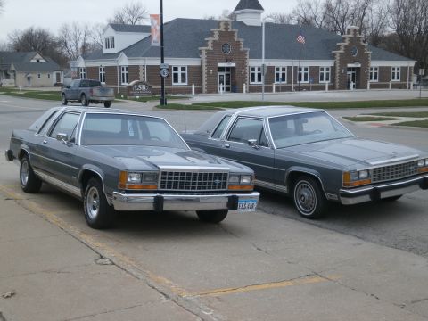
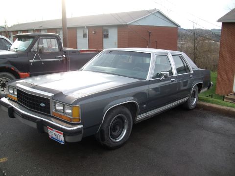
1985 Ford LTD Crown Victoria/
Photo
supermotors.net/registry/media/504734
1987 Ford Crown Victoria & Grand Marquis ATC A/C-Heater Wiring Diagram

1987 automatic temperature control electrical wiring showing blower motor, blower resistors, ATC servo programmer, A/C clutch and thermal limiter circuits with wire colors.
Part of 1983-1991 Ford LTD Crown Victoria Wiring Diagrams
This document is a Mitchell Repair Information Company wiring diagram (Fig. 19) for the Automatic Temperature Control (ATC) A/C-heater system on the 1987 Ford LTD Crown Victoria and Mercury Grand Marquis. It shows the complete electrical circuit for the automatic climate control system, including the thermal blower lockout switch, blower motor, ATC function switch (with OFF, VENT, PANEL, HI-LO, FLOOR, MIX, and DEFROST positions), blower switch (AUTO/LO/MED/HI), blower resistors with thermal limiter, ATC servo programmer (M1, M2, HI terminals), clutch cycle pressure switch, electronic control assembly (pins #10, #54, #37), A/C wide-open throttle relay (EFI), throttle kicker relay (carbureted engines), throttle kicker solenoid, diodes, and the A/C compressor clutch. Power feeds come through fuse #9 (BRN-ORG wire) and fuse #6 (WHT-PPL wire). Every wire color code is labeled, e.g., DK BLU-LT GRN, ORG, ORG-BLK, LT GRN-PPL, BLK-YEL, PNK-LT BLU, GRY-YEL, RED-LT GRN, and BLK-LT GRN, and the diagram distinguishes carbureted-only vs. EFI-only branches. A reader can use this diagram to trace circuits, identify wire colors at each component, and diagnose faults in the ATC blower, compressor clutch, and throttle kicker circuits. Printed page dated February 13, 2004; © 2003 Mitchell.
Is this accurate? Sign in to help verify it.
Frequently asked questions
- Which fuses power the ATC (automatic temperature control) system on the 1987 Crown Victoria?
- The diagram shows power feeding the ATC function switch through Fuse #9 on a BRN-ORG wire and Fuse #6 on a WHT-PPL wire. Amp ratings are not shown on this diagram.
- What wire colors go to the blower motor?
- The blower motor connects via an ORG wire and an ORG-BLK wire.
- What are the pin assignments at the electronic control assembly?
- Pin #10 is PNK-LT BLU, Pin #54 is ORG-LT BLU, and Pin #37 is RED.
- What positions does the ATC function switch have?
- OFF, VENT, PANEL, HI-LO, FLOOR, MIX, and DEFROST.
- How does the diagram differ between carbureted and EFI models?
- EFI models use an A/C Wide Open Throttle Relay (marked EFI ONLY), while carbureted models use a Throttle Kicker Relay and Throttle Kicker Solenoid (marked CARB ONLY), with the clutch circuit wire noted as LT GRN-PPL (or BLK-YEL).
Comments
More from this build










No comments yet.