Home/
Registry/
Ford/
LTD Crown Victoria/
1983-1991/
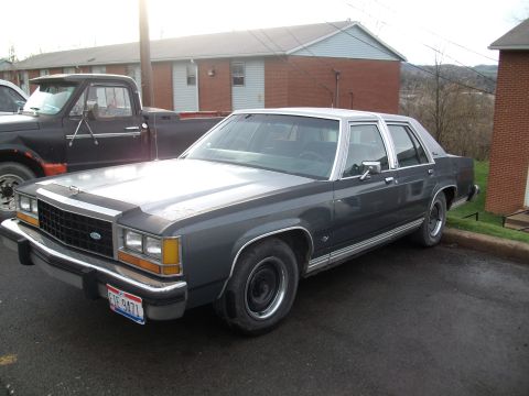
1985 Ford LTD Crown Victoria/
Photo
supermotors.net/registry/media/504721
Voltage Controlled Injector Waveform Pattern - 1987 Ford LTD Crown Victoria

Service manual injector-pattern tutorial page showing an oscilloscope waveform with labeled trace points.
Part of 1983-1991 Ford LTD Crown Victoria Manual Pages
This document is a single page from a Mitchell Repair Information "Waveforms - Injector Pattern Tutorial." It presents Fig. 2, "Identifying Voltage Controlled Type Injector Pattern," captured on a 1987 Ford LTD Crown Victoria. The page consists of an oscilloscope screen capture set to 10 volts per division (Ch1) with a 1 ms per division timebase. The waveform trace is annotated with five callout letters: A marks the flat supply-voltage level before injector activation; B marks the sharp voltage drop as the injector driver grounds the circuit; C marks the low on-time (grounded) portion of the trace; D marks the tall inductive voltage spike produced when the driver releases the circuit; and E marks the decaying shoulder as the voltage settles back to supply level. A trigger marker (T) sits on the spike and a channel 1 ground reference marker appears at the left edge. The page footer shows it was printed Friday, February 13, 2004 at 12:11 PM, is Page 1, and is copyright 2003 Mitchell Repair Information Company, LLC. A reference number, 95B23862, appears below the scope image. The page teaches readers what a voltage-controlled (saturated switch) type fuel injector waveform looks like on a lab scope.
Is this accurate? Sign in to help verify it.
Frequently asked questions
- What does this waveform diagram show?
- It is Fig. 2 from a Mitchell 'Waveforms - Injector Pattern Tutorial,' showing how to identify a voltage controlled type fuel injector pattern on an oscilloscope, captured on a 1987 Ford LTD Crown Victoria.
- What scope settings were used to capture this injector pattern?
- Channel 1 (Ch1) was set to 10 volts per division with a timebase of 1 ms per division (M 1ms).
- What do the letters A through E on the waveform indicate?
- They are callouts marking key parts of the voltage controlled injector trace: A the flat upper voltage level, B the sharp drop, C the low flat on-time portion near ground, D the tall voltage spike, and E the decaying shoulder after the spike.
- Who published this document and when?
- It is copyright 2003 Mitchell Repair Information Company, LLC, and the page footer shows it was printed Friday, February 13, 2004 at 12:11 PM (Page 1).
Comments
More from this build











No comments yet.