Home/
Registry/
Ford/
LTD Crown Victoria/
1983-1991/
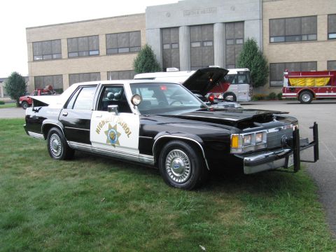
1985 Ford LTD Crown Victoria/
Photo
supermotors.net/registry/media/504732
1983 Ford Crown Victoria & Grand Marquis ATC A/C-Heater Vacuum Diagram

1983 automatic temperature control vacuum routing for Crown Victoria/Grand Marquis showing function-control valve, mode-door motors and temperature blend door.
Part of 1983-1991 Ford LTD Crown Victoria Vacuum Routing Diagrams
This document is a Mitchell Repair Information scan (printed February 13, 2004, © 2003) showing Fig. 6: the 1983 ATC (Automatic Temperature Control) vacuum diagram for the Ford Crown Victoria and Mercury Grand Marquis A/C-heater system, filed under a 1987 Ford LTD Crown Victoria heading. The diagram traces vacuum hose routing from the vacuum distribution source through the vacuum diverter valve, the harness vacuum connection block (HVCB), and function control connection block (FCCB) to the ATC function selector vacuum valve. Each hose is labeled by color: black, black/purple, black/red, black/yellow, black/blue, black/orange, black/tan, black/white, and black/turquoise. Vacuum motors and components identified include the floor-defrost door vacuum motor, panel full door vacuum motor, panel partial door vacuum motor, servo motor, in-car temperature sensor, temperature control lever, outside-recirculate door vacuum motor, and the thermal blower lockout switch (open below 120°F). Selector positions shown are Panel, Vent, Hi-Lo, Floor, Mix, Defrost, and Off. A lower cutaway locates the heater core, evaporator core, blower motor (-19805), floor-defrost door, panel doors, temperature blend door (cable controlled), and outside-recirc air door, with a legend defining V (vacuum), NV (no vacuum), and PV (partial vacuum).
This document covers 1983, which may differ from this 1985 Ford LTD Crown Victoria.
Is this accurate? Sign in to help verify it.
Frequently asked questions
- What vehicles does this ATC vacuum diagram cover?
- The figure is titled '1983 ATC Vacuum Diagram (Crown Victoria & Grand Marquis)' and appears under a 1987 Ford LTD Crown Victoria heading in the Mitchell repair information.
- What hose colors are used in the 1983 ATC vacuum system?
- Black, black/purple, black/red, black/yellow, black/blue, black/orange, black/tan, black/white, and black/turquoise, plus a black turquoise line to the thermal blower lockout switch.
- How does the thermal blower lockout switch operate?
- It is shown in the warm position; when cold (below 120°F) the switch is open and the valve is closed.
- What vacuum motors control the airflow doors?
- The floor-defrost door vacuum motor, panel full door vacuum motor, panel partial door vacuum motor, the outside-recirculate door vacuum motor, and a servo motor, with the temperature blend door being cable controlled.
- What do the abbreviations V, NV, and PV mean on the diagram?
- V = vacuum, NV = no vacuum, PV = partial vacuum. HVCB is the harness vacuum connection block and FCCB is the function control connection block.
Comments
More from this build









No comments yet.