Home/
Registry/
Ford/
LTD Crown Victoria/
1983-1991/
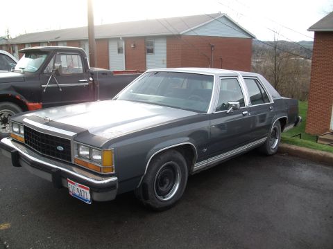
1985 Ford LTD Crown Victoria/
Photo
supermotors.net/registry/media/504727
Ford AOD Transmission Oil Circuit Diagram - 2nd Gear Part Throttle OD Range

Mitchell hydraulic oil circuit schematic for the Ford AOD automatic, 2nd gear (part throttle) in OD range, showing forward clutch applied and pressure-coded fluid paths.
Part of 1983-1991 Ford LTD Crown Victoria Schematics
This document is a hydraulic oil circuit diagram (Fig. 5) for the Ford AOD automatic transmission, showing fluid flow in 2nd Gear at Part Throttle in the "OD" (Overdrive) range. The header attributes it to a 1987 Ford LTD Crown Victoria and it was printed via a JV AUTO/MRIC service-information system (copyright 2003 MRIC, LLC; printed February 3, 2004). The schematic identifies which friction elements are applied in this operating state, the Intermediate Clutch and Forward Clutch are marked APPLIED, and traces oil passages between all major hydraulic components: pump, screen, sump, main oil pressure regulator valve, oil pressure booster valve, converter and converter relief valve, cooler and lube circuits, manual valve (P R N D 3 1), throttle valve/plunger/plug, governor assembly, 1-2/2-3/3-4 shift valves, shuttle, backout, accumulator, capacity modulator, orifice control, TV limit and TV relief valves, plus the OD and reverse servos and the reverse and direct clutches. A "Pressures" legend distinguishes Line, Governor, Throttle (T.V.), T.V. Limit, Regulated, Pump Inlet, and Converter pressures, plus exhaust and cooler/lube flow arrows. Reference number G97E03227 appears on the drawing. It is one page of a set covering the AOD in various gears and throttle positions, useful for diagnosing AOD shift and pressure problems.
Is this accurate? Sign in to help verify it.
Frequently asked questions
- Which clutches are applied in the Ford AOD in 2nd gear, part throttle, OD range?
- The diagram marks the Intermediate Clutch and the Forward Clutch as APPLIED in 2nd gear (part throttle) in the "OD" range.
- What hydraulic pressures are identified in the AOD oil circuit legend?
- The Pressures legend lists Line, Governor, Throttle (T.V.), T.V. Limit, Regulated, Pump Inlet, and Converter pressures, plus arrow symbols for Exhaust and Cooler And Lube flow.
- What valves are shown in the AOD 2nd gear oil circuit?
- The diagram shows the Main Oil Pressure Reg Valve, Oil Pressure Booster Valve, Converter Relief Valve, 1-2/2-3/3-4 Shift Valves, 3-4 Shuttle Valve, OD Servo Reg Valve, T.V. Limit Valve, T.V. Relief Valve, 1-2 Capacity and 2-3 Capacity Modulator Valves, 1-2 Accumulator Valve, 2-1 Sched. Valve, 2-3 TV Modulator Valve, 3-4 T.V. Modulator Valve, Low Servo Modulator Valve, 3-4 Backout Valve, 2-3 Backout Valve, Orifice Control Valve, Throttle Valve/Plunger/Plug, and the Manual Valve.
- What vehicle does this AOD diagram apply to?
- The document header states it is for a 1987 Ford LTD Crown Victoria (Ford AOD transmission).
- What positions does the AOD manual valve show?
- The manual valve is labeled with the positions P R N D 3 1.
Comments
More from this build








No comments yet.