Home/
Registry/
Ford/
LTD Crown Victoria/
1983-1991/
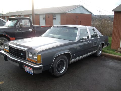
1985 Ford LTD Crown Victoria/
Photo
supermotors.net/registry/media/504715
1987 Ford LTD Crown Victoria 5.0L V8 Engine Oiling Circuit Diagram (VIN F & M)

Schematic of the engine oiling/lubrication circuit for a 5.0L V8 in a 1987 Ford LTD Crown Victoria.
Part of 1983-1991 Ford LTD Crown Victoria Schematics
This document is a single page from a Mitchell Repair Information Company service reference (printed February 13, 2004, © 2003), showing Fig. 13: Engine Oiling Circuit for the 1987 Ford LTD Crown Victoria. The page header identifies engine applicability as the 5.0L V8 (VIN code F) and the 5.0L HO V8 (VIN code M). The main content is a black-and-white cutaway line drawing of the V8 engine with directional arrows tracing the lubrication path: oil is drawn from the pickup in the oil pan, passes through the oil pump and filter, and is distributed through the main oil galleries in the block, up through the hydraulic lifters and hollow pushrods to the rocker arms and valvetrain at the cylinder head. The diagram itself carries no numbered callouts or part labels. Faint mirrored bleed-through from the reverse page (an exploded view of the valve lifter assembly with labels such as Push Rod Cup, Metering Valve Disc, Check Valve, Plunger, and Tappet Body) is visible but is not part of this page. A reader can learn the general oil flow routing through the 5.0L/5.0L HO V8 engine, useful when diagnosing low oil pressure or top-end lubrication issues.
This document covers 1987, which may differ from this 1985 Ford LTD Crown Victoria.
Is this accurate? Sign in to help verify it.
Frequently asked questions
- What does this diagram show?
- It is Fig. 13: Engine Oiling Circuit for the 1987 Ford LTD Crown Victoria, a cutaway drawing with arrows tracing oil flow from the oil pan pickup and pump through the block galleries, lifters, and pushrods up to the rocker arms.
- Which engines does this oiling circuit diagram apply to?
- Per the page header, it applies to the 5.0L V8 (VIN code F) and the 5.0L HO V8 (VIN code M).
- What is the source of this diagram?
- It is from Mitchell Repair Information Company, LLC (© 2003), printed Friday, February 13, 2004, Page 1.
- Does the diagram include labeled parts or torque specs?
- No. The illustration uses flow arrows only, with no printed callout labels, part numbers, or torque values on this page. Faint labels visible are bleed-through from the reverse page's valve lifter exploded view.
Comments
More from this build








No comments yet.