Home/
Registry/
Ford/
LTD Crown Victoria/
1983-1991/
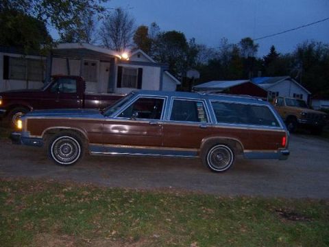
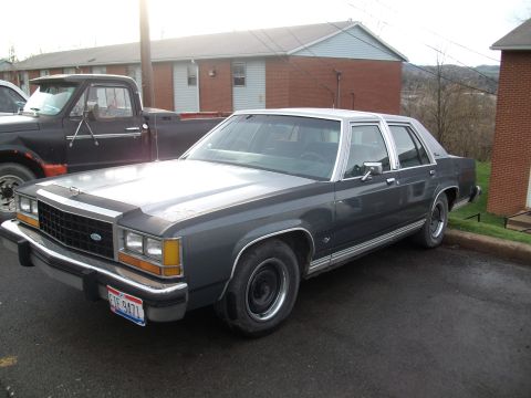
1985 Ford LTD Crown Victoria/
Photo
supermotors.net/registry/media/504720
Ford Injector Driver Types: Voltage vs Current Controlled - Waveform Tutorial

Schematic comparing voltage-controlled and current-controlled injector driver circuits (ECU, resistors, injectors) with current waveforms.
Part of 1983-1991 Ford LTD Crown Victoria Schematics
This document is page 1 of a Mitchell Repair Information waveform tutorial titled 'WAVEFORMS - INJECTOR PATTERN TUTORIAL,' with Figure 1 labeled 'Injector Driver Types - Current and Voltage' and attributed to a 1987 Ford LTD Crown Victoria. It illustrates the two basic fuel injector driver designs. Under 'Voltage-Controlled Type' it shows two circuit schematics: one using a solenoid (ballast) resistor in series with a low-resistance injector, and one using a high-resistance injector connected directly to battery voltage (+B), each switched to ground by a transistor inside the ECU. Under 'Current-Controlled Type' it shows a low-resistance injector driven by an ECU transistor with a current-sensing resistor, which limits current after opening. Below the schematics, a shared graph of current (A) versus time compares the resulting current waveforms for each driver type, with points A (transistor on) and B (injector open) marked on each trace; the current-controlled trace shows a high initial peak followed by a chopped/regulated lower hold current. The page carries Mitchell reference number 50G15053, a 2003 Mitchell Repair Information Company copyright, and a print date of Friday, February 13, 2004. It is part of a multi-page set that includes normal and excessive injector bank current-flow pages.
Is this accurate? Sign in to help verify it.
Frequently asked questions
- What are the two types of fuel injector drivers shown in this diagram?
- Voltage-controlled type and current-controlled type. The voltage-controlled type is shown in two versions: one with a solenoid resistor in series with a low-resistance injector, and one with a high-resistance injector connected directly to +B. The current-controlled type uses a low-resistance injector with a current-sensing resistor in the ECU driver circuit.
- What do points A and B mean on the current waveforms?
- Per the legend, A marks the point where the transistor turns on, and B marks the point where the injector opens.
- How does the current-controlled injector waveform differ from the voltage-controlled one?
- The graph shows the current-controlled type produces a sharp initial current peak followed by a lower, rapidly switched (chopped) hold current, while the voltage-controlled types show current rising smoothly to a steady plateau.
- Where does a voltage-controlled system with a low-resistance injector limit current?
- Through a solenoid resistor placed in series between +B and the low-resistance injector, with the ECU transistor switching the circuit to ground.
- What vehicle and source is this figure from?
- The figure is labeled for a 1987 Ford LTD Crown Victoria and is from Mitchell Repair Information Company, LLC (© 2003), figure reference 50G15053, printed February 13, 2004.
Comments
More from this build








No comments yet.