Home/
Registry/
Ford/
LTD Crown Victoria/
1983-1991/
1985 Ford LTD Crown Victoria/
Photo
supermotors.net/registry/media/504735
1987 Ford LTD Crown Victoria ATC Servo Motor Assembly Removal Diagram
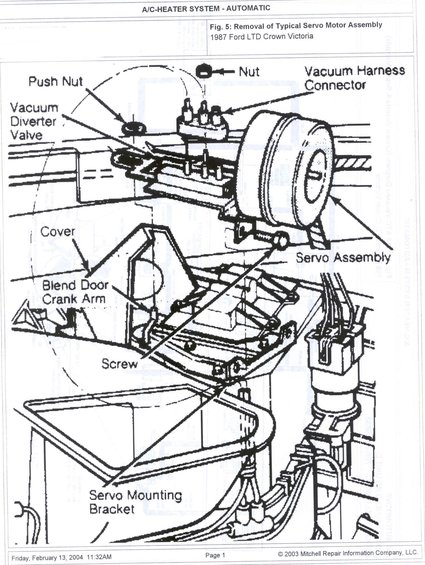
Mitchell service illustration showing removal of the automatic A/C-heater vacuum servo motor assembly: vacuum harness connector, diverter valve, blend door crank arm and mounting bracket.
Part of 1983-1991 Ford LTD Crown Victoria Exploded Parts Diagrams
This document is a single page from a Mitchell Repair Information Company service manual section titled "A/C-HEATER SYSTEM - AUTOMATIC." It presents Fig. 5, an exploded/labeled line illustration showing removal of a typical servo motor assembly for the automatic temperature control (ATC) system on a 1987 Ford LTD Crown Victoria. The illustration identifies the key components involved in servo motor removal and installation: the push nut, retaining nut, vacuum harness connector, vacuum diverter valve, cover, blend door crank arm, the servo assembly itself, mounting screws, and the servo mounting bracket. A reader can learn where the servo motor mounts relative to the blend door crank arm and heater/evaporator case, which fasteners (nut, push nut, screws) must be removed, and where the vacuum harness connector and vacuum diverter valve attach. Faint rotated text bleeding through from an adjacent page references an ATC vacuum diagram for the Crown Victoria and Grand Marquis. The page footer indicates it was printed on Friday, February 13, 2004 at 11:32AM, Page 1, © 2003 Mitchell Repair Information Company, LLC. No torque specifications, part numbers, or step-by-step written procedures appear on this page, it is purely a labeled component-location diagram.
Is this accurate? Sign in to help verify it.
Frequently asked questions
- What does this diagram show for the Ford LTD Crown Victoria?
- It shows Fig. 5, the removal of a typical servo motor assembly for the automatic A/C-heater (ATC) system on a 1987 Ford LTD Crown Victoria, with labeled components.
- What parts are labeled in the servo motor assembly diagram?
- Push Nut, Nut, Vacuum Harness Connector, Vacuum Diverter Valve, Cover, Blend Door Crank Arm, Servo Assembly, Screw, and Servo Mounting Bracket.
- What fasteners hold the ATC servo motor assembly in place?
- The diagram calls out a nut, a push nut, and screws securing the servo assembly to the servo mounting bracket.
- Where does the vacuum harness connect on the servo assembly?
- The diagram shows the vacuum harness connector attaching at the top of the servo/bracket area, near the vacuum diverter valve, secured by a nut.
- What is the source of this diagram?
- It is from Mitchell Repair Information Company, LLC (© 2003), under the section 'A/C-HEATER SYSTEM - AUTOMATIC', printed February 13, 2004.
Comments
More from this build











No comments yet.