Home/
Registry/
Ford/
LTD Crown Victoria/
1983-1991/
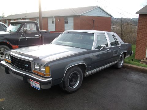
1985 Ford LTD Crown Victoria/
Photo
supermotors.net/registry/media/504716
Ford 5.0L V8 Valve Lifter Assembly Exploded Diagram - 1987 LTD Crown Victoria
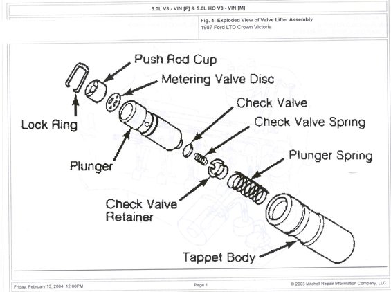
Mitchell exploded-view of the 5.0L V8 hydraulic valve lifter assembly: push rod cup, metering valve disc, plunger, check valve, springs and tappet body.
Part of 1983-1991 Ford LTD Crown Victoria Exploded Parts Diagrams
This document is a single-page exploded parts diagram from Mitchell Repair Information Company (printed February 13, 2004, © 2003) labeled 'Fig. 4: Exploded View of Valve Lifter Assembly' for a 1987 Ford LTD Crown Victoria. The header indicates it applies to the 5.0L V8 (VIN code F) and 5.0L HO V8 (VIN code M) engines. The line drawing shows a hydraulic valve lifter (tappet) disassembled along its axis, with arrows identifying nine components in assembly order: the lock ring and push rod cup at the top, followed by the metering valve disc, the plunger, the check valve, the check valve spring, the check valve retainer, the plunger spring, and finally the tappet body that houses the internals. A reader can learn the internal construction of the hydraulic lifter and the correct order and orientation of parts for disassembly, inspection, cleaning, or reassembly. No torque specifications, part numbers, or measurements appear on this page, it is purely an identification/orientation diagram. It is part of an album that also includes an engine oiling circuit diagram, suggesting it accompanies valvetrain/lubrication service information.
Is this accurate? Sign in to help verify it.
Frequently asked questions
- What engines does this valve lifter diagram cover?
- The header states it covers the 5.0L V8 (VIN F) and the 5.0L HO V8 (VIN M), shown for a 1987 Ford LTD Crown Victoria.
- What parts make up the valve lifter assembly in this diagram?
- The exploded view labels: push rod cup, lock ring, metering valve disc, plunger, check valve, check valve spring, check valve retainer, plunger spring, and tappet body.
- In what order do the internal lifter components sit inside the tappet body?
- From the top down the diagram shows: lock ring, push rod cup, metering valve disc, plunger, check valve, check valve spring, check valve retainer, plunger spring, then the tappet body housing everything.
- What part holds the check valve and its spring in place?
- The diagram shows a check valve retainer positioned after the check valve and check valve spring.
- Does this document give torque specs or part numbers for the lifter?
- No. It is an identification diagram only; no torque values, dimensions, or part numbers are shown.
Comments
More from this build









No comments yet.