1963-82 Chevy Corvette Control Arm Mounting Diagram - Upper & Lower A-Arm
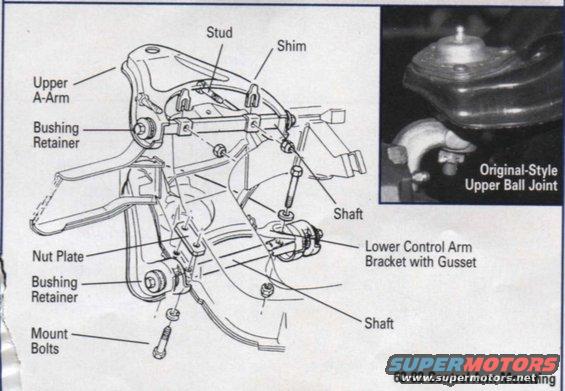
Exploded parts diagram of 1963-82 front suspension showing upper A-arm, ball joint, bushings, shims, and shafts.
This document is a labeled exploded-view diagram titled "63-82 Control Arm Mounting," covering the front control arm mounting arrangement for 1963–1982 Chevrolet Corvettes. The line drawing shows the upper A-arm and lower control arm area of the front suspension with callouts identifying key components: the upper A-arm, stud, shims used for alignment on the upper shaft, bushing retainers (shown at both the upper and lower arms), the upper and lower shafts, the nut plate, the lower control arm bracket with gusset, and the mount bolts. An inset photograph in the upper-right corner shows an "Original-Style Upper Ball Joint" as installed on the vehicle. A reader can learn how the upper and lower control arms attach to the chassis, where alignment shims are placed on the upper shaft, how bushing retainers and nut plates are positioned, and what the factory-original riveted-style upper ball joint looks like. The diagram contains no part numbers, torque specifications, or written instructions—only component identification labels—making it useful primarily for identifying parts during front suspension disassembly, rebuild, or restoration work on C2 and C3 Corvettes.
Is this accurate? Sign in to help verify it.
Frequently asked questions
- What components are shown in the 63-82 Corvette control arm mounting diagram?
- The diagram labels the upper A-arm, stud, shim, upper and lower shafts, bushing retainers, nut plate, lower control arm bracket with gusset, and mount bolts.
- Where do the alignment shims go on a 63-82 Corvette front suspension?
- The diagram shows shims located on the upper A-arm shaft, between the shaft and the mounting bracket area.
- What does the inset photo in this diagram show?
- It shows the original-style upper ball joint as installed on the upper control arm.
- How does the lower control arm mount on a 63-82 Corvette?
- Per the diagram, the lower control arm mounts via a shaft with bushing retainers to a lower control arm bracket with gusset, secured with a nut plate and mount bolts.
- What Corvette years does this control arm mounting diagram cover?
- The caption states it applies to 1963-82 models.
Comments
More from this build
No comments yet.