1965-1982 Chevy Corvette Rear Wheel Bearing Assembly Exploded Diagram
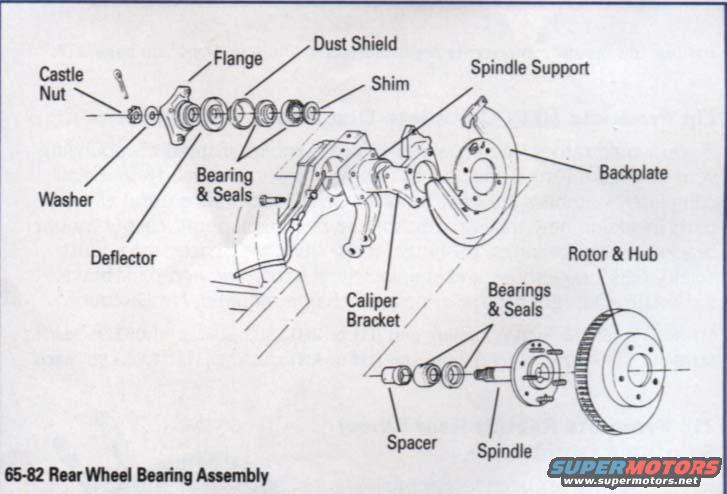
Exploded parts diagram of a 1965-82 rear wheel bearing assembly showing flange, bearings, seals, spindle, and rotor.
Part of 1968-1982 Chevrolet Corvette Exploded Parts Diagrams
This document is an exploded parts diagram of the rear wheel bearing assembly for 1965-1982 Chevrolet Corvettes, as stated in its caption '65-82 Rear Wheel Bearing Assembly.' The illustration shows how the rear hub and bearing components stack together on the independent rear suspension spindle support. On the inboard (flange) side, the diagram identifies the castle nut, washer, flange, bearing & seals, dust shield, shim, and deflector. The central component is the spindle support, to which the caliper bracket and backplate attach. On the outboard side, the drawing shows the spacer, inner and outer bearings & seals, the spindle itself, and finally the rotor & hub assembly. A reader can learn the correct order and orientation of every component in the rear wheel bearing stack-up, which parts sit between the flange and spindle support (including the adjustment shim), and where the caliper bracket and brake backplate mount relative to the spindle support. No part numbers, torque specifications, or adjustment procedures are given, this is purely a component-identification exploded view useful when disassembling, rebuilding, or reassembling a Corvette rear wheel bearing/spindle assembly.
Is this accurate? Sign in to help verify it.
Frequently asked questions
- What years of Corvette does this rear wheel bearing diagram cover?
- The caption states it covers 1965-1982 ('65-82 Rear Wheel Bearing Assembly').
- What parts make up the Corvette rear wheel bearing assembly in this diagram?
- The diagram labels the castle nut, washer, flange, bearing & seals, dust shield, shim, deflector, spindle support, caliper bracket, backplate, spacer, additional bearings & seals, spindle, and rotor & hub.
- Where does the shim go in the rear wheel bearing assembly?
- The shim is shown on the flange side of the assembly, positioned between the dust shield and the spindle support in the exploded stack-up.
- What sits between the two rear spindle bearings on a 65-82 Corvette?
- The diagram shows a spacer positioned between the bearings & seals on the spindle.
- Does this diagram include torque specs or part numbers?
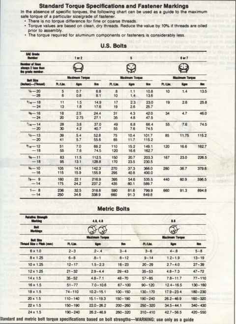
- No. It is an exploded component-identification diagram only; no torque values or part numbers are shown.
Comments
More from this build

No comments yet.