Home/
Registry/
Ford/
Mustang/
2005-2014/
“SHELBY GT500”/
Photo
supermotors.net/registry/media/673665
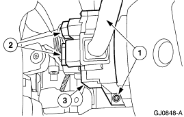
Ford Multifunction Switch Removal Diagram - Steering Column Connectors & Screws
Reference · 2005-2014 MustangAll 52 service procedures
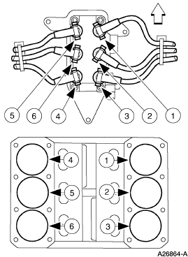
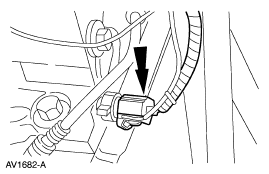
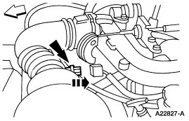
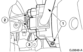
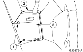
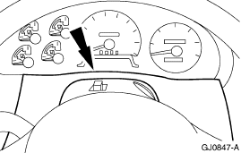
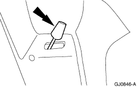
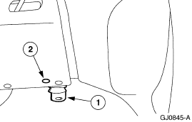









Service procedure figure identifying a switch assembly and its fasteners with numbered callouts.
Part of 2005-2014 Ford Mustang Service Procedures
This document is a single service-procedure illustration (figure number GJ0848-A) showing the multifunction switch mounted on a vehicle steering column, as filed in a SuperMotors.net album for a 2007 Ford Mustang (filename 'multifunction5.gif'). The line drawing depicts the steering column with the multifunction switch (turn signal/wiper stalk switch assembly) in place. Three numbered callouts identify components or steps: callout (2) points to two electrical connectors on the left side of the switch, callout (3) points to a retaining screw at the bottom of the switch, and callout (1) points to items on the right side of the assembly, apparently additional fasteners or the switch body/connector area. The image contains no accompanying legend, text instructions, torque specifications, or part numbers, so a reader can learn the general location of the multifunction switch, its electrical connectors, and its mounting screws, but must refer to other pages of the service procedure for step descriptions. Given the accompanying album files reference Ford truck systems (4R70W, 5.4 engine, F-150 brakes), this figure likely comes from a Ford workshop manual set, though the illustration itself states no year, model, or applicability.
Is this accurate? Sign in to help verify it.
Frequently asked questions
- What does this diagram show?
- It shows the multifunction switch mounted on the steering column, with numbered callouts identifying the electrical connectors (2), a retaining screw (3), and additional fastener/connector points (1).
- How many electrical connectors are shown on the multifunction switch?
- Callout (2) points to two electrical connectors on the left side of the switch.
- Where is the switch retaining screw located in the diagram?
- Callout (3) points to a screw at the lower portion of the multifunction switch.
- Does this document list torque specs or part numbers?
- No. The image contains only the illustration, callout numbers 1-3, and the figure reference GJ0848-A; no torque values or part numbers are shown.






No comments yet.