Home/
Registry/
Ford/
Mustang/
2005-2014/
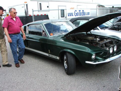
“SHELBY GT500”/
Photo
supermotors.net/registry/media/673664
Ford Multifunction Switch / Column Trim Panel Removal Illustration GJ0976-A

Reference · 2005-2014 MustangAll 52 service procedures
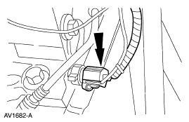
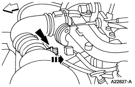
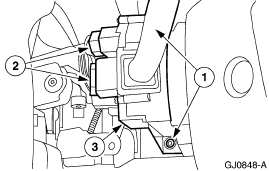
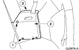
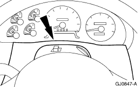
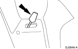
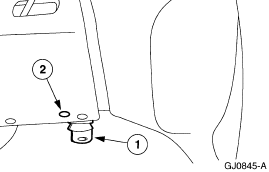
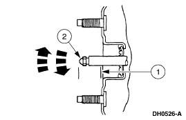
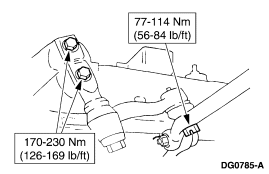
Service procedure figure showing a mounting bracket with numbered callouts for fasteners and attachment points.
Part of 2005-2014 Ford Mustang Service Procedures
This document is a single black-and-white service illustration (figure ID GJ0976-A) apparently taken from a Ford factory service procedure. It depicts an interior trim panel or shroud, likely part of a steering column or multifunction switch removal/installation procedure based on the uploader's filename 'multifunction4.gif', with three numbered callouts. Callout 1 (with arrows pointing to two locations along the bottom edge) indicates fastener or clip positions; callout 2 points to a slot or fastener location on the face of the panel; and callout 3 points toward the upper portion of the panel where it meets the surrounding structure. The illustration contains no legend, text descriptions, torque specifications, or part numbers, only the numeric callouts and the Ford-style figure reference number GJ0976-A. Because the legend page is not included in this scan, a reader can only learn the physical locations of the referenced attachment points, not their names or removal steps. The image appears to be one page of a multi-page procedure set uploaded by the vehicle owner; companion pages in the same album would likely contain the corresponding step text.
Is this accurate? Sign in to help verify it.
Frequently asked questions
- What does this diagram show?
- It is a service illustration (figure GJ0976-A) of an interior trim panel or shroud with three numbered callouts marking fastener/attachment locations: two at the bottom edge (callout 1), one on the panel face (callout 2), and one at the top (callout 3).
- Does this diagram list torque specs or part numbers?
- No. The only text visible is the callout numbers 1, 2, and 3 and the figure reference GJ0976-A. No torque values, part numbers, or legend text appear in this scan.
- How many fastener locations are indicated by callout 1?
- Callout 1 has arrows pointing to two locations along the bottom edge of the panel.
- What is the figure reference number of this illustration?
- GJ0976-A.
No comments yet.