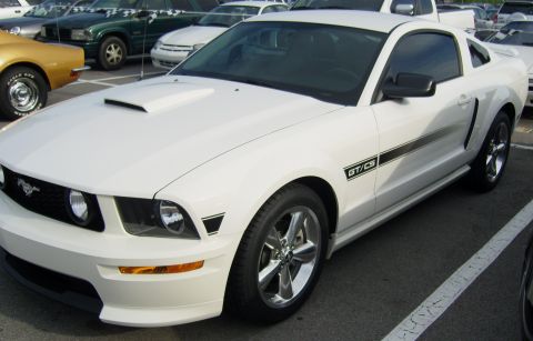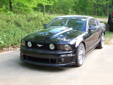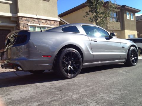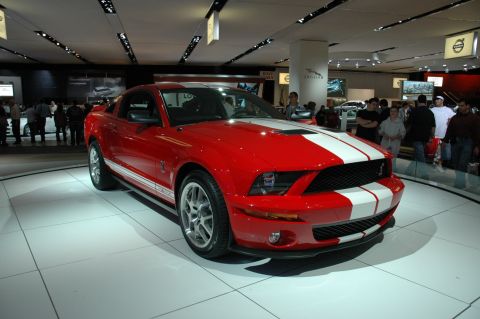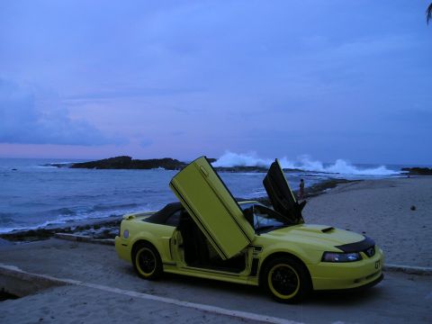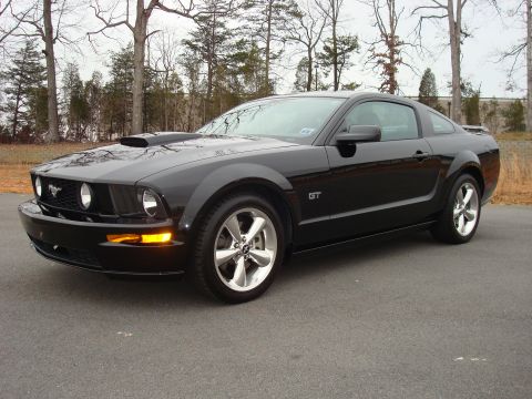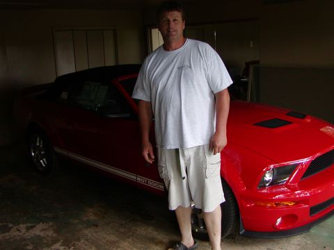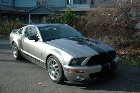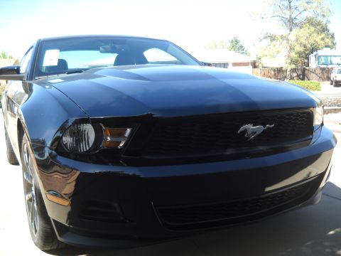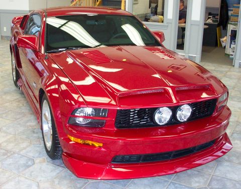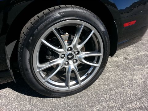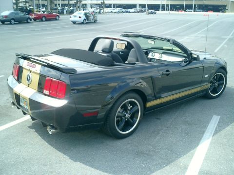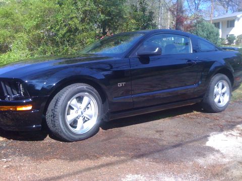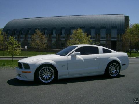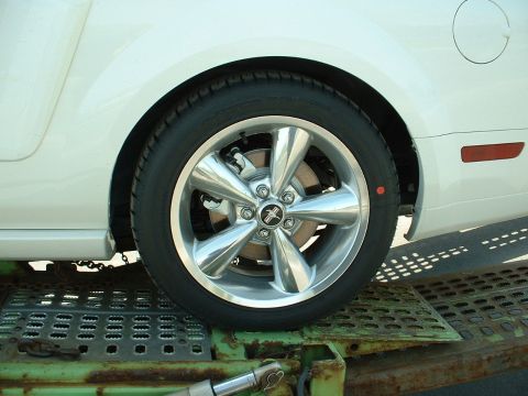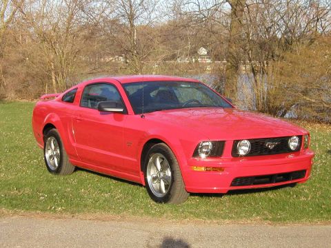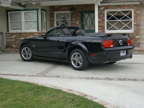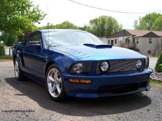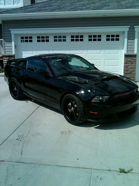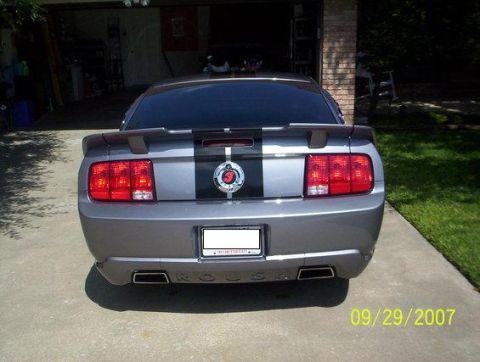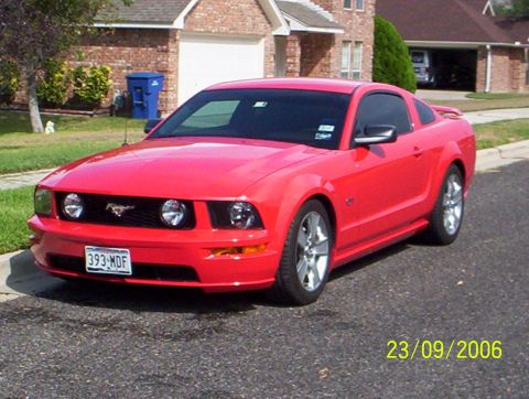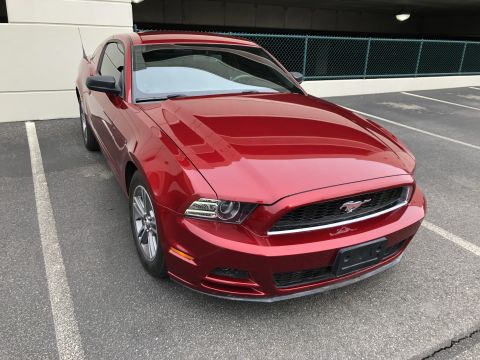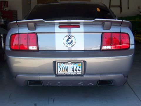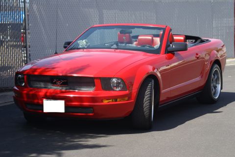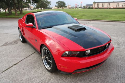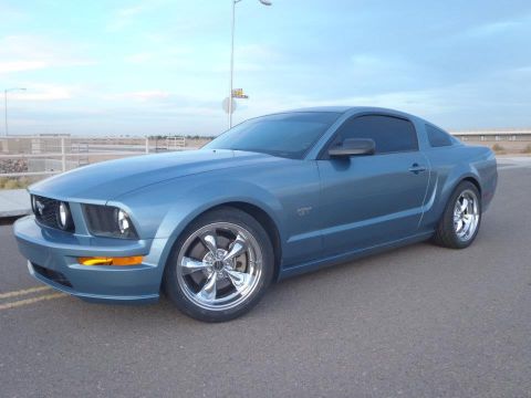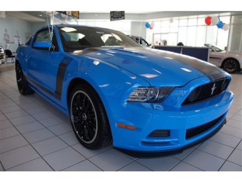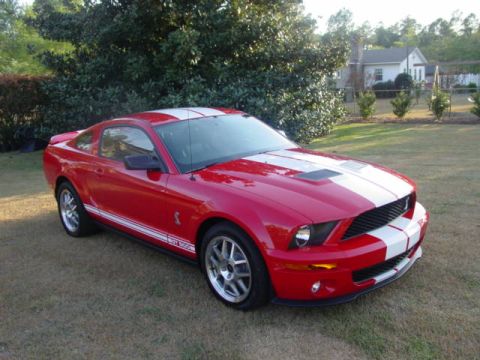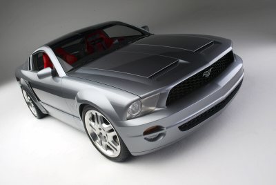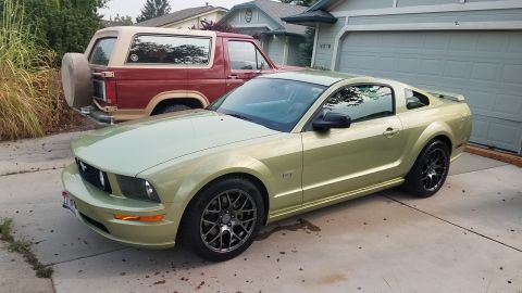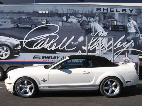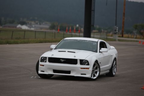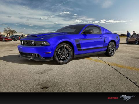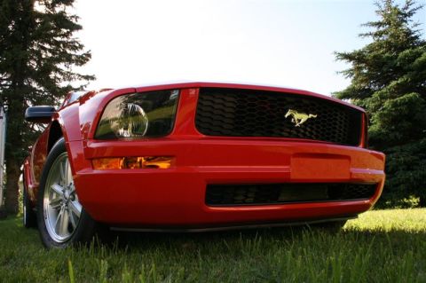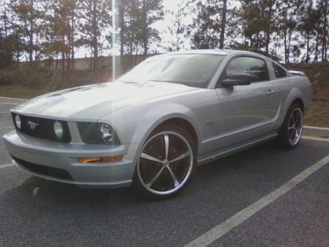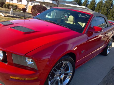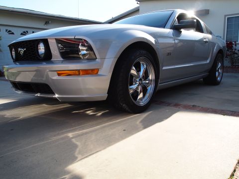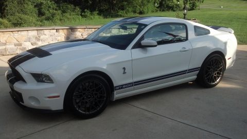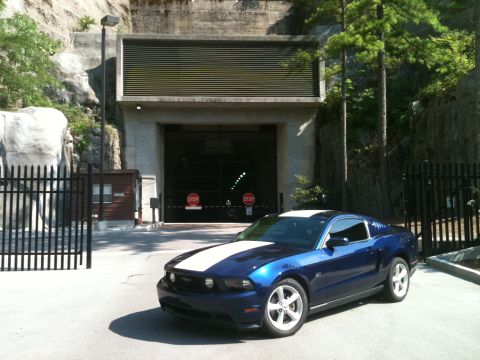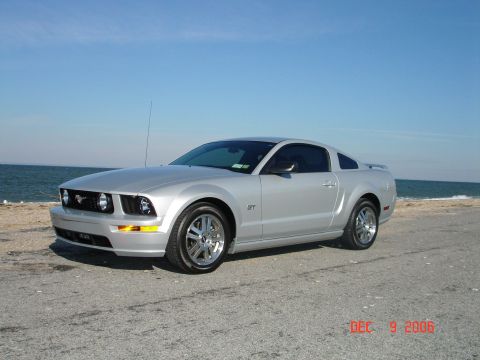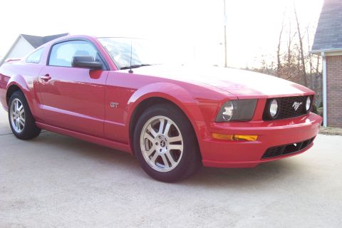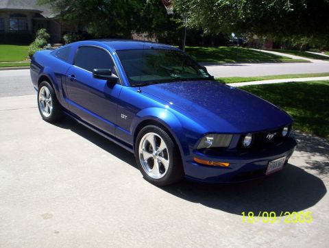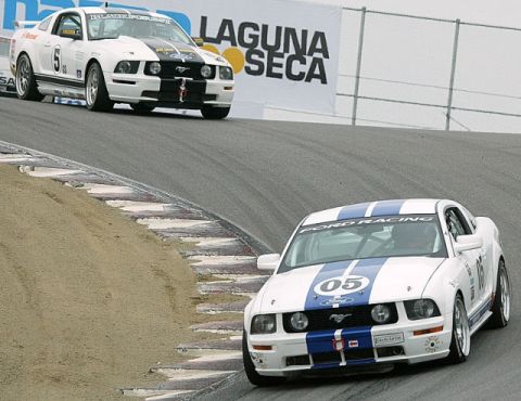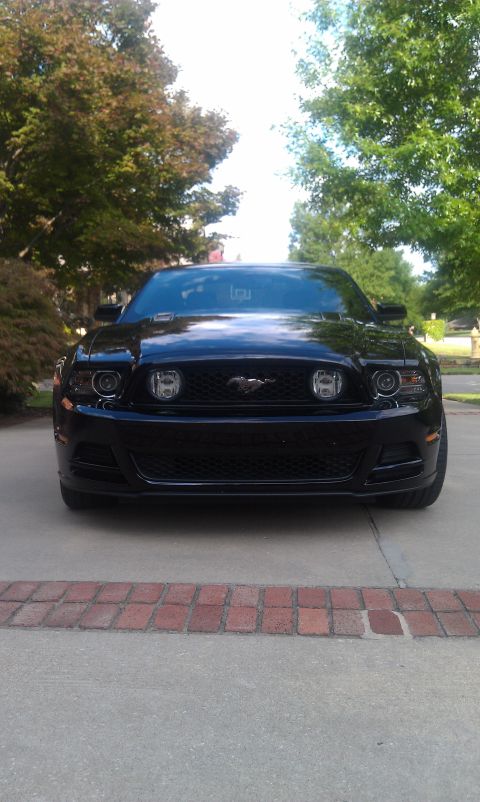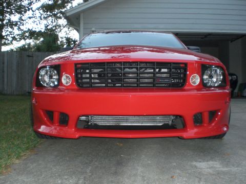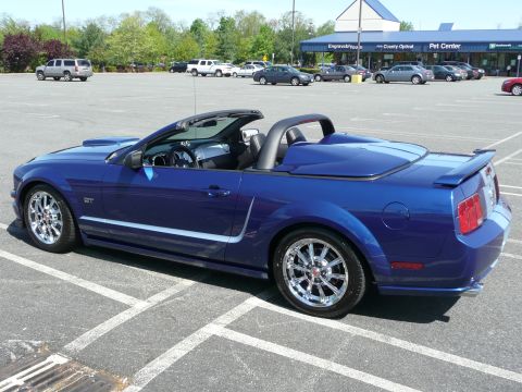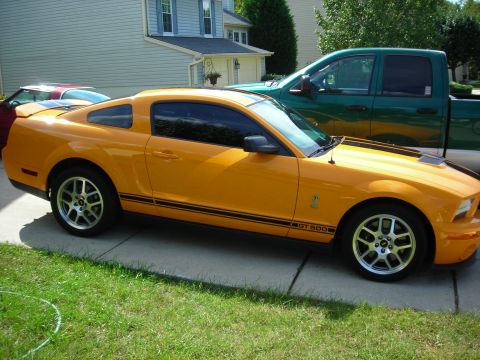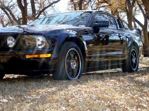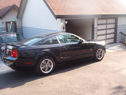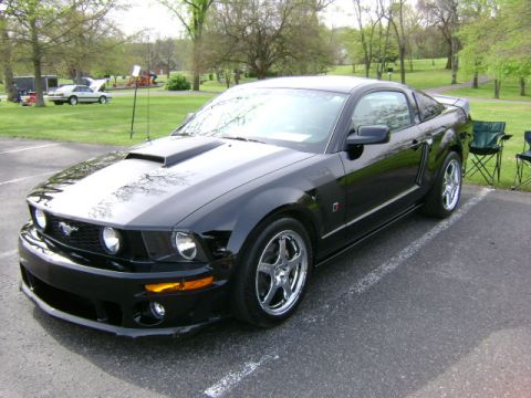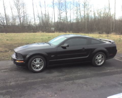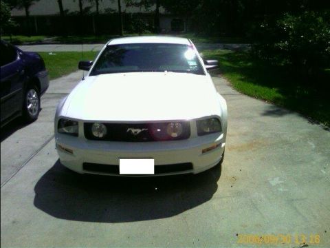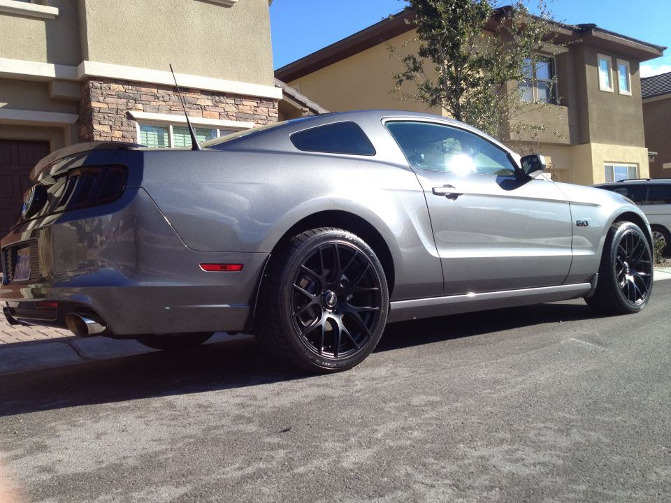
The fifth-generation Ford Mustang (2005-2014) used the new S197 platform, the first Mustang chassis not derived from the Fox architecture since the 1978 Mustang II. Ford styled it with retro cues drawn from the 1967-1968 fastback, including a long hood, short deck, and tri-bar taillamps. Underneath, the S197 kept a solid live rear axle located by a three-link setup with a Panhard rod, where the previous SVT Cobra had offered independent rear suspension. The 2005 launch paired a 4.0L SOHC V6 making 210 hp with a 4.6L 3-valve modular V8 rated at 300 hp. Over the run the line gained the supercharged Shelby GT500, the Bullitt, the 5.0L Coyote DOHC V8 that revived the 5.0 badge in 2011, the road-race Boss 302, and a 662 hp GT500. A 2010 restyle sharpened the shemetal but kept the S197 platform underneath through the final 2014 model year.
Other Ford Mustang generations
At a glance
- Years: 2005-2014 (fifth generation, S197)
- Platform: Ford S197, the first non-Fox-derived Mustang chassis since the Mustang II; solid live rear axle (three-link with Panhard rod) throughout
- Body styles: coupe and convertible
- Engines: 4.0L SOHC V6 (2005-2010), 3.7L DOHC V6 (2011+), 4.6L 3-valve modular V8 (2005-2010), 5.0L "Coyote" DOHC V8 (2011+), 5.4L then 5.8L supercharged V8 (Shelby GT500), road-race 5.0L (Boss 302)
- Performance models: GT, Shelby GT500 (from 2007), Bullitt (2008), Boss 302 (2012-2013)
- Horsepower basis: SAE net
Year-by-year changes
| Year | Key engines (SAE net) | Notable changes |
|---|---|---|
| 2005 | 4.0L SOHC V6 (210 hp); 4.6L 3-valve modular V8 (300 hp) | All-new S197 platform launches; retro 1967-1968 styling; solid live rear axle (three-link, Panhard rod); 5-speed manual or 5-speed automatic. |
| 2006 | 4.0L V6 (210 hp); 4.6L V8 (300 hp) | Carryover year; Pony Package added for V6 cars; convertible body style continued from the 2005 mid-year launch. |
| 2007 | 4.0L V6 (210 hp); 4.6L V8 (300 hp); Shelby GT500 5.4L supercharged DOHC V8 (500 hp) | Shelby GT500 returns as the range-topper with an Eaton-blown 5.4L and a Tremec TR-6060 6-speed; California Special (GT/CS) appearance package offered. |
| 2008 | 4.0L V6 (210 hp); 4.6L V8 (300 hp); Bullitt 4.6L V8 (315 hp); GT500 5.4L supercharged (500 hp) | Bullitt returns with 315 hp, dark exterior trim, and no rear spoiler; Shelby GT500KR (King of the Road) added with about 540 hp. |
| 2009 | 4.0L V6 (210 hp); 4.6L V8 (300 hp); GT500 5.4L supercharged (500 hp) | Glass-roof option added; final year of the 2005-2009 first S197 body before the restyle; GT500 carried over. |
| 2010 | 4.0L V6 (210 hp); 4.6L V8 (315 hp); GT500 5.4L supercharged (540 hp) | Major restyle (still S197); GT 4.6L raised to 315 hp; GT500 5.4L raised to 540 hp; revised interior and electronics. |
| 2011 | 3.7L "Cyclone" DOHC V6 (305 hp); 5.0L "Coyote" DOHC V8 (412 hp); GT500 5.4L aluminum-block supercharged (550 hp) | New 5.0L Coyote revives the 5.0 badge; 3.7L V6 replaces the 4.0L; 6-speed manuals across the line; GT500 gets an aluminum block (550 hp). |
| 2012 | 3.7L V6 (305 hp); 5.0L Coyote V8 (412 hp); Boss 302 5.0L (444 hp); GT500 5.4L supercharged (550 hp) | Boss 302 returns as a road-race model with a 444 hp version of the 5.0L; Boss 302 Laguna Seca added with track hardware. |
| 2013 | 3.7L V6 (305 hp); 5.0L Coyote V8 (420 hp); Boss 302 5.0L (444 hp); GT500 5.8L supercharged (662 hp) | Front-end refresh; GT 5.0L raised to 420 hp; new GT500 5.8L supercharged V8 makes 662 hp, the most powerful factory V8 of its time. |
| 2014 | 3.7L V6 (305 hp); 5.0L Coyote V8 (420 hp); GT500 5.8L supercharged (662 hp) | Final S197 model year; Boss 302 discontinued after 2013; carryover 3.7L V6, 5.0L GT, and Shelby GT500; replaced for 2015 by the S550 with standard independent rear suspension. |
The S197 platform and the return of the solid rear axle
The 2005 Mustang introduced the S197 platform, Ford's first Mustang chassis not derived from the Fox architecture that had underpinned the 1979-2004 cars. The S197 used a hydroformed front frame, MacPherson struts up front, and a solid live rear axle located by a three-link arrangement with a Panhard rod. Ford chose the live axle over independent rear suspension for cost and drag-strip traction, even though the 1999-2004 SVT Cobra had used IRS. This live-axle layout defined the entire 2005-2014 fifth generation; independent rear suspension did not become standard on the Mustang until the S550 arrived for 2015. The 2005 Mustang rode on a 107.1 in wheelbase, longer than the 101.3 in of the preceding SN95 cars.
The 2005-2010 4.0L V6 and 4.6L modular V8
At launch the 2005 Mustang base car used a 4.0L (245 cu in) SOHC V6, a Cologne-family engine rated at 210 hp. The 2005 Mustang GT used a 4.6L (281 cu in) 3-valve modular V8 making 300 hp and 320 lb-ft, the first 3-valve head on a modular Mustang engine and a step up from the 2-valve and DOHC 4.6L units of the SN95 era. The 2008 Bullitt used a tuned version of this 4.6L rated at 315 hp, fitted with an open-element cold-air intake, a revised calibration, and a freer-flowing exhaust, and wore dark trim with no rear spoiler in the manner of the 2001 Bullitt and the original 1968 Highland Green car. After the 2010 restyle, the 2010 Mustang GT 4.6L was raised to 315 hp.
The 2010 restyle and the 2011 Coyote 5.0L
The 2010 Mustang received a major exterior and interior restyle while keeping the S197 platform. The larger change came for 2011, when the Mustang GT adopted the new 5.0L (302 cu in) "Coyote" DOHC V8 rated at 412 hp and 390 lb-ft, reviving the 5.0 badge that had last appeared on the pushrod 302 of the Fox era. In the same year the base car replaced its 4.0L with a 3.7L (227 cu in) "Cyclone" DOHC V6 making 305 hp, and 6-speed manual transmissions arrived across the line. For 2013 the Coyote 5.0L was raised to 420 hp. The 2011-2014 5.0L cars paired the engine with a Getrag MT82 6-speed manual or a 6-speed automatic.
Shelby GT500, Bullitt, and Boss 302
The 2007 Mustang Shelby GT500 returned the GT500 name with a 5.4L (330 cu in) supercharged DOHC modular V8 rated at 500 hp, fed by an Eaton blower and backed by a Tremec TR-6060 6-speed manual. The 2008 Shelby GT500KR (King of the Road) raised output to about 540 hp. The 2010 GT500 5.4L was rated at 540 hp, and for 2011 the GT500 switched to an aluminum block that cut weight and raised output to 550 hp. The 2012 Mustang Boss 302 returned as a road-race model, using a high-revving 444 hp cross-plane-crank version of the 5.0L Coyote (the "RoadRunner" engine) with CNC-ported heads, revised cams, and a short-runner intake (sometimes called a "runners-in-the-box" manifold), and a Laguna Seca trim added stiffer suspension and a cross-car brace. For 2013 the Shelby GT500 received a 5.8L (351 cu in) supercharged V8 rated at 662 hp, the most powerful factory V8 of its time and the high-water mark of the S197 generation.
Known characteristics and weak points
The 2005-2010 4.6L 3-valve Mustang V8 is known for occasional spark-plug seizing and two-piece plug breakage on early modular 3-valve heads, a service concern Ford addressed with revised plug designs. The 2011-2014 5.0L Coyote cars paired with the Getrag MT82 manual drew complaints of notchy or balky shift quality in early examples. The solid live rear axle across the whole 2005-2014 run gives the fifth-generation Mustang strong straight-line traction but less compliant ride and handling over rough surfaces than the independent rear suspension that followed on the 2015 S550. Convertible bodies, offered throughout the generation, add weight and reduce structural rigidity relative to the coupe.
Frequently asked questions
What platform is the 2005-2014 Mustang built on?
The 2005-2014 Mustang uses the S197 platform, Ford's first Mustang chassis not derived from the Fox architecture since the 1974-1978 Mustang II. The S197 carried a solid live rear axle on a three-link setup with a Panhard rod for the entire fifth generation. Independent rear suspension did not become standard until the 2015 S550.
When did the 5.0L Coyote V8 return to the Mustang?
The 5.0L "Coyote" DOHC V8 arrived in the 2011 Mustang GT, rated at 412 hp and 390 lb-ft, and reviving the 5.0 badge last used on the Fox-era pushrod 302. The 2011 model year also replaced the 4.0L V6 with a 3.7L "Cyclone" V6 (305 hp) and added 6-speed manuals. The Coyote 5.0L was raised to 420 hp for 2013.
How much power did the 2013-2014 Shelby GT500 make?
The 2013-2014 Mustang Shelby GT500 used a 5.8L (351 cu in) supercharged DOHC V8 rated at 662 hp, the most powerful factory V8 of its time. Earlier S197 GT500 cars used a 5.4L supercharged V8 making 500 hp (2007-2009), then 540 hp (2010), then 550 hp with an aluminum block (2011-2012).
What was the 2012 Boss 302?
The 2012 Mustang Boss 302 returned the Boss 302 name as a road-race model, using a 444 hp cross-plane-crank version of the 5.0L Coyote V8 (the "RoadRunner" engine) with CNC-ported heads, revised cams, and a short-runner intake (sometimes called a "runners-in-the-box" manifold). A Boss 302 Laguna Seca variant added stiffer suspension, a cross-car brace, and track-focused hardware. The Boss 302 was offered for 2012 and 2013 only.
Why does the fifth-generation Mustang use a solid rear axle?
Ford fitted the 2005-2014 S197 Mustang with a solid live rear axle, located by a three-link and Panhard rod, for cost and drag-strip traction rather than the independent rear suspension the 1999-2004 SVT Cobra had used. The trade-off is less ride compliance over rough roads. The Mustang did not get standard independent rear suspension until the 2015 S550 generation.
Sources
- Ford Motor Company factory specifications, press materials, and model-year brochures (2005-2014 Mustang, GT, Bullitt, Shelby GT500, Boss 302).
- Period road tests and technical reviews from automotive enthusiast publications.
- Shelby American and Ford SVT documentation for GT500, GT500KR, and Boss 302 variants.
- Mustang owner and marque-club reference material for service notes and known weak points.
Asked all the time
What platform is the 2005-2014 Mustang built on?
The 2005-2014 Mustang uses the S197 platform, Ford's first Mustang chassis not derived from the Fox architecture since the 1974-1978 Mustang II. The S197 carried a solid live rear axle on a three-link setup with a Panhard rod for the entire fifth generation. Independent rear suspension did not become standard until the 2015 S550.
When did the 5.0L Coyote V8 return to the Mustang?
The 5.0L "Coyote" DOHC V8 arrived in the 2011 Mustang GT, rated at 412 hp and 390 lb-ft, reviving the 5.0 badge last used on the Fox-era pushrod 302. The 2011 model year also replaced the 4.0L V6 with a 3.7L "Cyclone" V6 (305 hp) and added 6-speed manuals. The Coyote 5.0L was raised to 420 hp for 2013.
How much power did the 2013-2014 Shelby GT500 make?
The 2013-2014 Mustang Shelby GT500 used a 5.8L (351 cu in) supercharged DOHC V8 rated at 662 hp, the most powerful factory V8 of its time. Earlier S197 GT500 cars used a 5.4L supercharged V8 making 500 hp (2007-2009), then 540 hp (2010), then 550 hp with an aluminum block (2011-2012).
What was the 2012 Boss 302?
The 2012 Mustang Boss 302 returned the Boss 302 name as a road-race model, using a 444 hp cross-plane-crank version of the 5.0L Coyote V8 (the "RoadRunner" engine) with CNC-ported heads, revised cams, and a short-runner intake (sometimes called a "runners-in-the-box" manifold). A Boss 302 Laguna Seca variant added stiffer suspension, a cross-car brace, and track-focused hardware. The Boss 302 was offered for 2012 and 2013 only.
Why does the fifth-generation Mustang use a solid rear axle?
Ford fitted the 2005-2014 S197 Mustang with a solid live rear axle, located by a three-link and Panhard rod, for cost and drag-strip traction rather than the independent rear suspension the 1999-2004 SVT Cobra had used. The trade-off is less ride compliance over rough roads. The Mustang did not get standard independent rear suspension until the 2015 S550 generation.
Technical Reference
Member-uploaded diagrams & documents for this generation. AI-classified; community-verified where badged.
Data/Spec Plates (10)
- 2007 Ford Mustang Shelby GT500 Door Jamb Labels - VIN, Tire & Loading PlacardThis is a photograph of the driver's door-jamb labels on a Ford Mustang Shelby GT500. Three labels are visible. The left label is a bilingual (English/French) Shelby GT500 tire advisory stating that the original…
- 2007 Ford Shelby GT500 Convertible Flat Rock Loose Item Checklist Label - VIN 1ZVHT89S7This is a factory shipping/loose-item checklist label from Ford's Flat Rock Assembly Plant (marked 'FLAT ROCK / WRAP ACCEPTANCE'), attached to a new vehicle at build time. The 'LOOSE ITEM CHECKLIST' lists items shipped…
- 2007 Ford Shelby GT500 Convertible Flat Rock Loose Item Checklist Label - VINThis document is a Ford factory shipping/quality label from the Flat Rock assembly plant, titled 'Loose Item Checklist' with 'Flat Rock Wrap Acceptance'. It lists the loose items shipped with the vehicle: fixed…
- 2007 Ford Shelby GT500 Convertible Window Sticker - MSRP, Options & SpecsThis document is the original factory window sticker (Monroney label) for a 2007 Ford Shelby GT500 Convertible, VIN 1ZVHT89S775225037. It describes a 4-passenger sports car with a 5.4L supercharged 4-valve V8 engine…
- 2007 Ford Shelby GT500 Convertible Window Sticker - MSRP, Options & EPA MPGThis document is the original Monroney window sticker (and adjacent smog/bumper/parts-content label) for a 2007 Ford Shelby GT500 Convertible, VIN 1ZVHT89S775225037, in Torch Red Clearcoat with Black w/Red Accent…
- 2013 Ford Mustang GT Roush Stage III Window Sticker - MSRP, Options & EPA DataThis image shows the factory Monroney window sticker for a 2013 Ford Mustang GT Coupe (5.0L 4V Ti-VCT V8, 6-speed manual MT82), exterior Black with Charcoal Black cloth bucket interior, assembled at Flat Rock and sold…
- Ford Mustang Cobra Convertible Driver LH Red Seat Part Label - L0074080AJ265R7This is a photograph of two adjacent parts/packaging labels attached to a black plastic bag, apparently containing a driver-side (left-hand) seat or seat cover component for a Cobra convertible Mustang. Both labels…
- Ford Mustang Cobra Convertible RH Passenger Part Label - P/N L0074081AR095R7This photograph shows two factory parts labels affixed to a clear plastic bag containing an automotive component, apparently photographed as-purchased inside a vehicle. Both labels carry the same Build Sequence Number…
- 2007 Ford Mustang Window Sticker - Smog Index, Bumper & Parts Content LabelThis document is a portion of a factory window sticker (Monroney label) scanned for a Ford Mustang, containing three federally required disclosure sections. The Smog Emissions Information section states the vehicle's…
- Ford Mustang Window Sticker: Smog Index, Bumper Label & Parts Content InfoThis document is a portion of a Ford window sticker (Monroney label) showing three federally required disclosure sections. The Smog Emissions Information section states this vehicle's SMOG Index is 0.49 compared to the…
Brochures & Literature (42)
- Ford Mustang Car Show Judged Classes List (1964½–2014) & Specialty AwardsThis document is a car show class sheet listing the judged classes for a Ford-powered car show, with First, Second, and Third Place awards. A table defines 30 classes by year range and description, covering Mustangs…
- 35th Annual Mustang & All Ford Show 2014 Flyer - Music City Mustang Club, TNThis document is a promotional flyer and registration form for the 35th Annual Mustang and All Ford Show, hosted by the Music City Mustang Club and celebrating Mustang's 50th Anniversary (1964–2014). The event took…
- 2012 TN Valley Mustang Club 23rd Annual Mustang & All-Ford Show FlyerThis is a registration flyer for the Tennessee Valley Mustang Club's 23rd Annual Mustang & All-Ford Show, held October 20 & 21, 2012 at Ray Varner Ford, 2026 N. Charles G Seivers Blvd., Clinton, TN 37716 (about one…
- Muscle Car Ministries Fall Car Show Flyer - Lance Cunningham Ford, Knoxville TNThis document is a promotional flyer (event poster) for the Muscle Car Ministries "Fall Car Show," presented by Lance Cunningham Ford of Knoxville, TN. The event is scheduled for September 15th, running from 10 a.m. to…
- 2013 Keeneland Concours d'Elegance Flyer - Ford Mustang Featured MarqueThis document is a promotional flyer for the 2013 Keeneland Concours d'Elegance (spelled "d'Elagance" in the title), held July 20, 2013, at the Keeneland Race Course in Lexington, Kentucky, where the Ford Mustang was…
- Mustang Round Up 2012 Flyer - Crazy Horse Mustang Club, Owensboro KY Car ShowThis document is a promotional flyer/card for the "Mustang Round Up" car show hosted by the Crazy Horse Mustang Club of Owensboro, Kentucky. The event was held on Saturday, September 22, 2012, rain or shine, at…
- 2011 Nashville-Area Car Show Program: 36 Judged Classes & Sponsor ListThis document is a page from a 2011 car show program/brochure (apparently from a show in the Nashville/Franklin, Tennessee area). It lists the show's 36 judged vehicle classes, ranging from Domestic Production classes…
- 23rd Annual Antique & Classic Car Show Flyer - Cool Springs Galleria, Franklin TN 2012This document is a promotional flyer for the 23rd Annual Antique & Classic Car Show held at Cool Springs Galleria in Franklin, Tennessee, on Saturday, October 6, 2012, adjacent to the Sears Automotive Center. The show…
- Gladefest Antique Car Show 2012 Flyer - Classes & Fees, Mt. Juliet TN (AACA)This document is a flyer for the Gladefest Antique Car Show, held Saturday, September 15, 2012, in the lot next to Gladeville Church of Christ at 1435 Gladeville Road, Mt. Juliet, TN 37122. The show was organized by…
- 5th Annual CrossWay Baptist Church Car Show Flyer - Aug 25, 2012 Murfreesboro TNThis document is a promotional flyer for the 5th Annual CrossWay Baptist Church Car Show, held August 25th, 2012, in Murfreesboro, Tennessee. The event opens at 9:00am, with registration ending at noon and trophies…
- Freedom Church Car Show Flyer 10/13/2012 - Gallatin TN Cars, Trucks & BikesThis document is a promotional flyer for a car show event held on October 13, 2012, at Freedom Church, 1010 Freedom Church Rd., Gallatin, TN 37066. The show welcomes all cars, trucks, and bikes with classes for each…
- 2012 Old Skool & New Kool Car, Truck & Bike Show Flyer - Nashville TNThis document is a promotional flyer and registration form for the "Old Skool and New Kool Car, Truck, & Bike Show," held September 15, 2012, at Broadmoor Family Worship Center, 215 Broadmoor Drive, Nashville, TN…
- 5.0 Mustang & Super Fords September 2012 Cover - 2013 Shelby GT500 First DriveThis is the front cover of the September 2012 issue of 5.0 Mustang & Super Fords magazine, a Source Interlink Media publication. The cover story is a first drive of the 2013 Shelby GT500, described as 'burning rubber…
- Car Show Registration Form & 48 Class List - Lebanon TN Meet (Wilson Bank)This document is a car show pre-registration form and rules sheet, apparently for a classic/collector car meet in Lebanon, Tennessee. The left column lists the show's ground rules (safety glass, fire extinguisher, and…
- 6th Annual SummerFest & Antique Car Show Flyer - Wilson Bank & Trust, Murfreesboro TNThis document is a promotional flyer for the 6th Annual SummerFest & Antique Car Show, hosted at Wilson Bank & Trust, 3110 Memorial Blvd., Murfreesboro, TN 37129 (phone 904-6350). The event takes place on Sunday, June…
- Cruise In Bikes & Rods Car Show Flyer - June 16, 2012, Nashville TNThis document is not a vehicle service or reference document; it is a promotional flyer for a car and motorcycle show called "Cruise In: Bikes & Rods." The event was held on Father's Day weekend, Saturday, June 16…
- Mustang Mania at the Downs 2012 Flyer - Kentucky Downs, Franklin KY Car ShowThis document is not a technical reference but a promotional "Hold the Date" flyer for the Mustang Mania at the Downs car show, hosted by the Franklin-Simpson Chamber of Commerce and presented by Hunt Ford Chrysler…
- March Madness Car Show & Drag Race Flyer - Clarksville Speedway, March 26, 2011This document is an event flyer for the "March Madness Car Show & Drag Race," a 5th Anniversary Event presented by Clarksville Speedway on March 26, 2011, in Clarksville, Tennessee. Admission is $5 at the gate with…
- 2008 Ford Racing Performance Parts Catalog Cover - American StampedeThis image shows the front cover of the Ford Racing 2008 Performance Parts catalog, subtitled "American Stampede," priced at $5.00 USA. The cover is dominated by a large photo of a blue-and-white Ford Mustang FR500GT3…
- How to Customize Your Ford F-150 Truck 1997-2008 - HPBooks / Truckin' MagazineThis is a photograph of the front cover of a paperback book titled "How to Customize Your Ford F-150 Truck, 1997–2008," published by HPBooks and compiled from the editors of Truckin' Magazine. The cover features a…
- 2001 Ford F-150 Wiring Diagrams Manual - Ford Motor Company CoverThis image shows the front cover of an official Ford Motor Company publication titled "2001 Wiring Diagrams" for the F-150. The cover is a light gray/marbled card with the Ford Motor Company script logo at the top in…
- 2003 Ford Light Truck Parts Catalog Vol 3 GCAT - Aviator, Blackwood, EscapeThis is a photograph of the front cover of the 2003 Ford Light Truck Parts Catalog, Volume 3 – GCAT Vehicles, published by the Ford Customer Service Division. The cover is dated December 2002 with a 2002 copyright, and…
- 2003 Ford Car & Truck Engine/Emission Facts Book Summary - Cover ScanThis image shows the front cover of the 2003 Ford "Car & Truck Engine/Emission Facts Book Summary," an official Ford Motor Company publication. The cover is dark red with white text, features a stylized globe graphic…
- 2000 Ford Car & Truck Engine/Emission Facts Book Summary - CoverThis image is a photograph of the front cover of a Ford publication titled "2000 Car & Truck Engine/Emission Facts Book Summary." The cover is pale green with white text and concentric circle graphics radiating from a…
- ATSG Update Handbook Cover - Ford AODE, 4R70W, 4R75E Techtran ManualThis is a photograph of the front cover of an ATSG (Automatic Transmission Service Group) Update Handbook, part of the Techtran Manual series. The cover identifies the transmissions covered: the Ford AODE, 4R70W, and…
- ATSG Ford/Mercury AODE Transmission Techtran Manual - Cover ScanThis is a photograph of the front cover of an ATSG (Automatic Transmission Service Group) Techtran™ Manual for the Ford/Mercury AODE automatic transmission. The cover features the ATSG logo in the upper left, a banner…
- OBD II Diagnostic Strategies Manual - Scan Tool, DTC & Freeze Frame GuideThis image shows the front cover of a spiral-bound automotive training/reference manual titled "OBD II Diagnostic Strategies." The cover lists the major topics addressed inside the book: Tech Tips, Using DTCs…
- Ford Electronic Returnless Fuel Systems Training Manual LBT-86 - Team A.V.I.This image shows the front cover of a spiral-bound (comb-bound) automotive training manual from Team A.V.I. (Automotive Video, Inc.), titled "LBT-86: Ford Electronic Returnless Fuel Systems." The cover features the…
- 1998 Ford Selected Vehicles New Model Training Reference Book FCS-12823-98-REFThis image shows the front cover of a Ford factory training publication: the "1998 Selected Vehicles Body, Chassis, Electrical, and Powertrain Features — New Model Training Reference Book." The cover carries the Ford…
- AVI Understanding Air Conditioning Diagnostic Strategies Training Manual CoverThis image shows the front cover of a spiral-bound (comb-bound) automotive training booklet titled "Understanding Air Conditioning Diagnostic Strategies," produced by Team A.V.I. (Automotive Video, Inc.). The cover…
- 2004 Ford 6.0L Diesel Powertrain Control/Emissions Diagnosis Service Manual CoverThis image shows the front cover of a Ford factory service publication: the "6.0L Diesel Powertrain Control/Emissions Diagnosis 2004 Service Manual." The cover is black with gold horizontal accent stripes, the title…
- 1997 Ford Powertrain Product Guide Cover - Engines, Transmissions, AxlesThis image shows the front cover of the 1997 Ford Powertrain Service Engineering Product Guide. The cover, photographed lying on white fabric, is a three-hole-punched booklet with a gray pinstriped background. The year…
- MOTOR Crash Estimating Data Oct 2004 Ford Motor Company - Vol 36 No 11 CoverThis image shows the front cover of a MOTOR Crash Estimating Data guide (the well-known collision-industry estimating reference published by MOTOR Information Systems, carrying the tagline 'Where To Go When You Need To…
- 2001 Ford 7.3L Powerstroke Diesel Powertrain Control/Emissions Diagnosis ManualThis image shows the front cover of a Ford Motor Company factory service publication: the "7.3L Powerstroke Diesel Powertrain Control/Emissions Diagnosis 2001 Service Manual." The cover is black with tan/gold…
- 2004 Ford F-150 Heritage Factory Wiring Diagrams Manual - CoverThis is a photograph of the front cover of a genuine Ford Motor Company factory service publication: the 2004 Wiring Diagrams manual for the Ford F-150 Heritage. The cover is Ford's standard green wiring-diagram binder…
- Building & Tuning High-Performance Electronic Fuel Injection Book - SA Design SA83This image is a photograph of the front cover of the book "Building & Tuning High-Performance Electronic Fuel Injection" by Ben Strader, published by S-A Design (catalog number SA83). The cover describes the book as…
- How to Build Supercharged & Turbocharged Small-Block Fords by Bob McClurgThis image is a photograph of the front cover of the book "How to Build Supercharged & Turbocharged Small-Block Fords" by Bob McClurg, published by S-A Design (CarTech's SA Design imprint). The cover advertises the…
- Maximum Dyno at Bellevue Cruise-In Flyer - 1 May 2010, Bellevue Center MallThis document is a promotional flyer for a car cruise-in event held on 1 May 2010 from 5pm to 9pm, featuring the "Maximum Dyno" at the Bellevue Cruise-In. The event took place at Sears in the Bellevue Center Mall…
- 1997-2003 Ford F150 Select Restoration Flyer - King Ranch, Lightning, HarleyThis document is a one-page promotional flyer or brochure cover titled "F150 Select 1997-2003." It advertises a business specializing in the mechanical restoration of 1997-2003 Ford F150 pickup trucks and their…
- 1999 Ford Light Truck Parts Catalog Volume 2 Illustrations - Cover & IndexThis is a photograph of the front cover of the 1999 Ford Light Truck Parts Catalog, Volume 2 – Illustrations, published by the Ford Customer Service Division. The cover features a light blue panel with the title and a…
- 1999 Ford Light Truck Parts Catalog Vol 1 Text Part 2 of 2 - Cover & IndexThis is a photograph of the front cover of the 1999 Ford Light Truck Parts Catalog, Volume 1 — Text, Part 2 of 2, published by Ford Customer Service Division (Form FCS 7753-99-LD, dated December 1998, copyright 1998)…
- 1997 Ford F-150 New Model Training Reference Book - Dealer Cover ScanThis image shows the front cover of a Ford dealership/technician publication titled the '1997 New Model Training Reference Book' for the Ford F-150 pickup truck. The cover features a large black-and-white photograph of…
Exploded Parts (43)
- Amsoil Ea Oil Filter Exploded Diagram - Components & Construction ExplainedThis document is an exploded-view diagram of an "Ea" brand spin-on oil filter, showing the filter disassembled into its individual components with labeled callouts describing each part's function. Nine components are…
- 2007 Ford Mustang Supercharger/Intercooler Exploded Parts Diagram (N0076038)This document is an exploded-view parts illustration (figure reference N0076038) showing the disassembly/assembly relationship of what appears to be a supercharger or intake manifold assembly with an integrated…
- 2007 Ford Mustang Supercharger & Fuel Rail Exploded Diagram - Torque SpecsThis is an exploded parts diagram (Ford illustration number N0085974) showing the disassembly/assembly of a supercharger and fuel rail installation on a V8 engine. Numbered callouts 10 through 19 identify components…
- Ford 4x4 Front Axle Exploded Parts Diagram DE1629-A - Differential AssemblyThis document is an exploded parts diagram, identified by the Ford-style drawing reference code DE1629-A. It depicts a front drive axle assembly of the type used on 4x4 trucks, showing the differential carrier/housing…
- 1997 Ford F150/F250 Steering Column Exploded Parts Diagram - Floor Shift FixedThis document is a page from a Ford Master Parts Catalog illustration section (Light Truck, Illustration Section 35, page 5, illustration P-31462). It shows an exploded parts diagram of the steering column for floor…
- Ford 4.6L Romeo V8 Engine Exploded Parts Diagram - Component Callouts 1-60This document is an exploded parts illustration of a V8 engine assembly, showing the relative positions of all major internal engine components. Numbered callouts 1 through 60 identify individual parts, including…
- 1997 Ford F150/F250 & Expedition Heater Blower Exploded Parts DiagramThis document is a scanned page (Illustration Section 184, page 22) from a Ford 'Light Truck' parts illustration catalog. It presents an exploded-view diagram titled 'Heater, Blower & Related Parts' applicable to the…
- Ford Instrument Panel Exploded Diagram - Dash Trim & Bezel Components GR3173-AThis document is an exploded parts illustration of an automotive instrument panel (dashboard) assembly, identified by drawing reference GR3173-A. The main dashboard assembly (item 4) is shown in the center, with leader…
- Ford EVAP System & Fuel Tank Component Diagram - Canister & Line Routing AV0800-BThis document is a Ford factory-style illustration (figure code AV0800-B) depicting an exploded/component layout of a truck fuel tank and its associated evaporative emission (EVAP) and fuel line routing. Eleven…
- Ford Transfer Case Exploded Parts Diagram - Callouts 39-71 (C11718-B)This document is an exploded-view parts illustration, uploaded as 'transfercase2.gif' and apparently depicting a transfer case assembly (likely one page of a multi-page set, as the '2' in the filename suggests). The…
- Ford Transfer Case Exploded Parts Diagram - Component Callouts (C11717-B)This document is an exploded-view parts illustration of a transfer case assembly, labeled with figure code C11717-B. It contains no written legend, table, or part names—only numbered callouts (1 through 38, with…
- Ford In-Tank Fuel Pump & Sender Assembly Diagram - Sock, Float, Pulse DamperThis document is a labeled exploded/line-art illustration of an in-tank fuel pump and sender assembly. The drawing shows the assembly hanging from its circular tank flange, with callouts identifying the major…
- Ford Fuel Pump Module Diagram - Fuel Tank Pressure Sensor & Regulator LocationThis document is a black-and-white line illustration of a fuel pump module / fuel sender assembly, shown removed from the fuel tank. The drawing depicts the round tank flange (lock ring mounting plate) at the top with…
- Ford 4x4 Components Diagram E9673-A - Axle Actuator & Line Routing IllustrationThis document is a single-page illustration (figure ID E9673-A) showing an automotive component layout with nine numbered callouts. The upper portion of the diagram depicts components mounted near a vehicle frame or…
- Ford Steering Column Exploded Parts Diagram - Assembly View GG0538-BThis document is an exploded-view parts illustration of a complete steering column assembly, identified by the figure reference number GG0538-B in the lower right corner. The drawing shows the steering column…
- Ford Transmission Ring Gear Speed Sensor Trigger: Previous vs New Design (ATS)This document is a side-by-side technical illustration comparing two versions of an automatic transmission ring gear, labeled "Previous Design" and "New Design." The left drawing shows the earlier ring gear, which uses…
- Ford 9.75 Rear Axle & Limited-Slip Differential Exploded Parts DiagramThis document is an exploded parts diagram (drawing reference A0009195) of a Ford rear axle/differential assembly, uploaded as "9.75 Diff" to a 2007 Ford Mustang gallery. The illustration contains no text labels…
- Ford 5.4L V8 Engine Exploded Diagram - Block, Crankshaft, Pistons & Oil PanThis document is an exploded parts illustration (Ford figure ID A0043129) of a V8 engine lower end / short block assembly. The drawing shows the cylinder block (callout 1) with numbered callouts 1 through 23 pointing…
- Ford Rear Drum Brake Exploded Parts Diagram GH1195-A - Shoes, Springs, AdjusterThis document is an exploded-view parts diagram of a rear drum brake assembly, identified only by the illustration number GH1195-A in the lower right corner. It shows the backing plate, wheel cylinder, brake shoes…
- 2001 Ford F-150 Front Seat Captain Chairs Power Track Exploded Parts DiagramThis document is a factory exploded-parts illustration (drawing number P-38807, dated 11/28/2001) for the 2001 Ford F-150 front seat, specifically the captain chairs with power track and seat-integrated restraints. It…
- Ford Supercharger Exploded Diagram - Blower, Gaskets & Lower Intake (GV1565-C)This document is an exploded parts diagram (figure ID GV1565-C) showing the disassembly/assembly relationship of a supercharger (blower) and its related intake components. The illustration depicts, from top to bottom…
- Ford Front Wheel Hub & Bearing Exploded Diagram (GH1364-A) - Outer BearingsThis document is a Ford service-manual style exploded parts illustration (figure ID GH1364-A) showing the disassembly sequence of a front wheel hub and bearing assembly. The drawing depicts a hub and disc brake rotor…
- Ford Front Rotor Hub Bearing & Seal Exploded Diagram GH1365-AThis document is a single exploded-parts line drawing (figure ID GH1365-A) showing a front disc brake rotor and hub assembly with five wheel studs, along with two components removed and exploded outward from the hub…
- Ford Rear Drum Brake Exploded Parts Diagram (LH Shown) - Illustration H9932-AThis document is an exploded-view parts illustration of a rear drum brake assembly, labeled "REAR (L H SHOWN)" with a "FRONT" orientation arrow and Ford illustration number H9932-A. The drawing contains 27 numbered…
- Ford 5.4L V8 Engine Exploded Parts Diagram - Intake, Injectors, Coils (A0055202)This document is an exploded parts illustration from a Ford service reference showing the upper engine assembly components of a V8 engine (uploaded and labeled by the owner as a 5.4L engine diagram). The drawing…
- Ford 5.4L V8 Engine Exploded View Diagram - Heads, Camshafts & ManifoldsThis document is a single exploded parts illustration of a V8 overhead-cam engine, identified only by the Ford illustration reference number A0051325 in the lower-left corner. The drawing shows the engine's major…
- Ford 5.4L V8 Engine Exploded Diagram - Water Pump, Oil Filter, Rear Seal, FlywheelThis document is an exploded parts diagram illustrating a Ford V8 engine (labeled in the uploader's album as a 5.4L engine, page 3 of a multi-page set). The upper illustration shows the engine block assembly viewed…
- Ford 5.4L Engine Front Cover & Timing Chain Exploded Parts Diagram (A0043130)This document is a single exploded-view parts illustration (figure reference A0043130) depicting the front-end/timing components of a V-type Ford engine. The drawing shows the engine cylinder block at right with the…
- Ford 5.4L V8 Engine Exploded Diagram - Block, Crankshaft, Pistons & Oil PanThis document is a single-page exploded parts illustration of an engine short block assembly, uploaded as '5.4 ENGINE-1.gif'. It shows a V-type cylinder block (callout 1) with a piston, piston rings, wrist pin…
- Ford 4x4 Front Suspension Exploded Parts Diagram - Hub, Axle Shaft, Control ArmsThis document is an exploded-view parts illustration (Ford illustration reference GF0794-A) showing front suspension and four-wheel-drive (4x4) front axle components on a truck frame. The line drawing depicts, in…
- Ford 4x4 Front Disc Brake Exploded Diagram - Knuckle, Caliper, Rotor (GH1180-A)This document is an exploded-view parts illustration of a front disc brake assembly, most likely from a Ford factory service manual (the only visible text is the Ford-style illustration reference number "GH1180-A")…
- Ford Front Door Window Regulator & Glass Exploded Diagram with Torque SpecsThis document is an exploded parts diagram (reference code A0100622) showing the front door glass, window regulator, and related door components for a Ford vehicle. The illustration depicts a door shell with the…
- 2004 Ford F-150 2WD Front Disc Brake Exploded Diagram - Torque SpecsThis document is an exploded parts diagram of a front disc brake assembly and associated brake hose/line routing, identified by figure number A0084814. The main illustration shows the steering knuckle, splash shield…
- 2007 Ford Mustang Supercharger Assembly Exploded Diagram - Torque Spec N0071919This document is a single exploded-view/component-location line drawing, figure reference N0071919, uploaded to a 2007 Ford Mustang gallery with the filename 'SC1.gif'. It depicts what appears to be a…
- 2007 Ford Mustang Coolant Pump Exploded Diagram - Hoses, Bracket & Torque SpecThis document is an exploded parts illustration (Ford service-manual style, figure number N0052641) showing the installation of an auxiliary coolant pump assembly and its related hoses, mounting bracket, and electrical…
- Ford 5.4L Intake Manifold Bolt Location Diagram (11 Bolts) - A0040506This document is a single-page technical illustration, apparently from a Ford factory service manual, showing an intake manifold viewed from above with eleven numbered callouts (1 through 11). The callouts point to…
- 2001 Ford F150 Sliding Sunroof Exploded Parts Diagram & Roof Panel DiagnosisThis photograph shows two open Ford factory reference books. The left book is a Ford Light Truck parts illustration catalog (Illustration Section 400, page 18) displaying an exploded-view diagram of the sliding sun…
- Ford 4.6L V8 Intake Manifold & Gasket Exploded Parts Diagram (A0013524)This document is a black-and-white exploded parts illustration showing an intake manifold assembly for an overhead-cam V8 engine. The upper portion of the drawing shows the complete intake manifold assembly (callout 1)…
- Ford Transmission Valve Body Diagram AD1405-A - Component Callout IllustrationThis document is a single-page line-art illustration (figure number AD1405-A) showing what appears to be an automatic transmission valve body or control body assembly viewed from one face. Four numbered callout…
- Ford Seat Belt Retractor Mounting Diagram - Service Tool 501-010 (A0030872)This document is a single black-and-white line illustration from a Ford service manual showing the removal or installation of a seat belt retractor assembly at a vehicle's B-pillar/quarter area. The drawing depicts the…
- Ford ECT Engine Coolant Temperature Sensor Diagram - Connector Views (A24392-A)This document is a simple line-art illustration of an automotive sensor, uploaded with the filename "ECT.gif," suggesting it depicts an Engine Coolant Temperature (ECT) sensor. The drawing shows two views of the…
- Ford 4R100 Transmission Check Ball Locations Diagram - Valve Body PlateThis document is a line-art diagram of an automatic transmission valve body plate (separator/spacer plate) showing the locations of nine numbered items, most likely check balls, per the uploader's filename…
- Ford Crankshaft Position Sensor Ring (Trigger Wheel) Diagram - A0032166This document is a single black-and-white exploded-parts style illustration from what appears to be a Ford factory service manual, identified by the Ford illustration reference number A0032166 in the lower-left corner…
Service Procedures (38)
- Ford Supercharger Bolt Tightening Sequence Diagram (Fig. N0049439)This document is a single service-procedure illustration (figure number N0049439) depicting a supercharger assembly mounted atop an engine intake area. The diagram uses ten circled numbered callouts (1 through 10)…
- 2007 Ford Mustang Supercharger/Intake Bolt Tightening Sequence DiagramThis document is a single technical line-art illustration, apparently one page of a multi-page Ford service procedure set. It depicts a top-down view of an engine component — based on the filename (SC5.gif) and…
- 2007 Ford Mustang Supercharger Intercooler Diagram - Callout Locations N0049440This document is a single exploded/callout illustration (Ford figure number N0049440) showing a rectangular finned core — consistent with an intercooler or charge air cooler — seated inside a larger housing, likely a…
- Ford Hub Service Procedure Illustration DF0558-A - Hub & Fastener Install DiagramThis document is a single line-art service illustration (figure reference DF0558-A) from a Ford factory service procedure. The image shows a close-up exploded/installation view of what appears to be a wheel hub or…
- Ford Service Illustration F8870-A - Hub/Axle Component Callout DiagramThis document is a single black-and-white line-art service illustration bearing the Ford figure reference code F8870-A. It shows an underbody/front-axle area component assembly—consistent with a hub, axle, or…
- Ford Hub/Wheel End Service Illustration F8857-B - Callout DiagramThis document is a single line-art service illustration labeled F8857-B, showing a close-up view of a vehicle component area with two numbered callouts. Callout (1) points to a small fastener or fitting on the…
- Ford Front Wheel Hub & Steering Knuckle Diagram - Service Illustration GF0810-AThis document is a single service-procedure illustration showing a front wheel hub and steering knuckle assembly, viewed from the outboard side with the brake rotor removed and wheel studs visible. Two numbered…
- Ford Headlamp Assembly Removal Diagram - Retainer Pins & Connector (GN0906-A)This document is a single exploded-view line illustration showing removal or installation of a headlamp assembly from the front of a vehicle. The drawing depicts the front corner of the vehicle structure (radiator…
- Ford Cable Routing & Connector Diagram GH0923-A - Service IllustrationThis document is a single black-and-white service illustration labeled with Ford figure number GH0923-A. It depicts a cable (consistent with the uploader's filename 'cable.gif') routed along the lower body/rocker area…
- Ford Blower Motor Removal Diagram - Mounting Screw Locations (A0073389)This document is a single service-procedure illustration (Ford figure ID A0073389) depicting a blower motor assembly as installed in the vehicle. The line drawing shows the blower motor mounted in the HVAC housing with…
- Ford Door Latch Actuator Cable Illustration GN3042-A - Service Procedure FigureThis document is a single black-and-white line-art illustration from a Ford service procedure, showing a door latch/actuator assembly with an attached cable. A large black arrow points to the cable connection area at…
- Ford Actuator Service Illustration GN2626-A - Mounting/Connector Points DiagramThis document is a single black-and-white line-art service illustration bearing the Ford graphics number GN2626-A. It contains no other text, legend, callout numbers, torque values, or part numbers. The drawing shows a…
- Ford Door Lock Actuator Mounting Screw Torque Diagram (10-14 Nm) - GN2627-AThis document is a single-page service illustration showing the fastener locations and torque specification for a component mounted inside a vehicle door — based on the upload filename, a door lock/latch actuator. The…
- Ford Door Actuator & Linkage Service Illustration GN3036-A - Callout DiagramThis document is a single black-and-white line illustration from a Ford service publication, identified by the figure reference code GN3036-A in the lower right corner. The drawing shows a portion of a vehicle door or…
- Ford Door Actuator Bolt Torque Spec Diagram - 12 Nm (9 lb-ft) Service IllustrationThis document is a single service illustration showing the inner side of a vehicle door with the door trim panel removed, exposing the internal door frame, window regulator/latch mechanism area, and hardware access…
- Ford PCV Hose Location Diagram - Rear of Engine Service Illustration (AA4459-A)This document is a single black-and-white line-art illustration from a Ford factory service publication, identified by the illustration reference code AA4459-A. It depicts the rear area of an engine as viewed in the…
- Ford 4.2L Rear Main Seal Removal Diagram - Tools 100-001 & 303-519This document is a single service-procedure illustration showing removal (or installation) of an engine crankshaft rear main oil seal. The line drawing depicts the rear face of an engine block/rear cover with the seal…
- Ford 4.2L V6 Lower Intake Manifold Installation Diagram - Sealer Points A26859-AThis is a service illustration (figure A26859-A) showing an intake manifold installation procedure, most likely the lower intake manifold of a V6 engine. The drawing contains three views: at the top, an exploded view…
- Ford Crankshaft Position Sensor Ring Installation Diagram (A0032166)This document is a single line-art service illustration showing the installation or orientation of a crankshaft sensor ring (crankshaft position sensor pulse/trigger wheel) on the front of an engine's crankshaft. The…
- Ford Seat Latch Assembly Diagram - Service Illustration R12243-AThis document is a single line-art service illustration, identified by the Ford figure number R12243-A, uploaded with the filename 'Seat latch.gif'. It depicts a latch or bracket mechanism — apparently a seat latch…
- Ford 4.2L V6 Cylinder Numbering & Spark Plug Wire Routing Diagram (A26864-A)This scanned service illustration shows the cylinder numbering and spark plug wire routing for a Ford V6 engine (filed as '4.2 order' by the uploader). The upper diagram depicts the coil pack/wire terminal area viewed…
- Ford 4.2L CHT Sensor Location Diagram - Service Illustration AV1682-AThis document is a single black-and-white line-art service illustration bearing the Ford illustration reference number AV1682-A. It depicts a section of an engine with surrounding wiring harnesses and hoses, and a…
- Ford IAT Sensor Location Diagram - Intake Air Temperature Sensor & ConnectorThis document is a single-page service illustration (Ford graphic reference A22827-A) showing the location of a sensor mounted in the engine air intake tube — consistent with the upload filename 'IAT.gif', it depicts…
- Ford Multifunction Switch Removal Diagram - Steering Column Connectors & ScrewsThis document is a single service-procedure illustration (figure number GJ0848-A) showing the multifunction switch mounted on a vehicle steering column, as filed in a SuperMotors.net album for a 2007 Ford Mustang…
- Ford Multifunction Switch / Column Trim Panel Removal Illustration GJ0976-AThis document is a single black-and-white service illustration (figure ID GJ0976-A) apparently taken from a Ford factory service procedure. It depicts an interior trim panel or shroud—likely part of a steering column…
- Ford Instrument Cluster / Multifunction Switch Location Diagram GJ0847-AThis document is a single black-and-white line-art illustration, identified by the Ford artwork reference number GJ0847-A, of the type typically found in Ford workshop manual service procedures. The drawing shows a…
- Ford Multifunction Switch Lever Location Diagram - Steering Column IllustrationThis document is a single black-and-white line-art illustration from a Ford service procedure, uploaded under the filename 'multifunction2.gif'. The drawing depicts a portion of a vehicle's steering column and dash…
- Ford Service Illustration GJ0845-A - Component Location Callout DiagramThis document is a single black-and-white service illustration (Ford figure reference GJ0845-A) showing a section of vehicle bodywork or interior panel with two numbered callouts. Callout 1 identifies a cylindrical…
- Ford Brake Booster Mounting Stud Diagram DH0526-A - Service IllustrationThis document is a single service-procedure illustration (Ford illustration ID DH0526-A) uploaded under the filename 'booster.gif'. The image shows a close-up cutaway/side view of a flanged component mounted to a panel…
- Ford RABS Sensor Location & Removal Illustration E10054-A - Service DiagramThis document is a single black-and-white line-art service illustration, identified by the Ford illustration reference number E10054-A. It depicts a component—based on the upload filename, related to the RABS (Rear…
- Ford Shift Motor Removal Illustration C11699-A - Connector & Mounting BoltsThis document is a black-and-white line-art service illustration, identified only by the Ford illustration reference number C11699-A. It depicts a motor assembly — per the uploader's filename, a transfer case shift…
- Ford 4x4 Shift Motor Electrical Connector Diagram - Service Illustration C11698-AThis document is a single service-procedure illustration (Ford figure number C11698-A) showing an electrical connector and its mating component, marked with two numbered callouts (1 and 2). The drawing depicts a…
- Ford Transfer Case Shift Motor Mounting Bolts Diagram - Service IllustrationThis document is a single illustration from a Ford service procedure, identified by the figure code C11696-A. The uploader filed it as "shift motor 3" — apparently one page of a multi-page shift motor (transfer case…
- Ford 4x4 Transfer Case Shift Motor Connector Location Diagram (C11695-A)This document is a single black-and-white line illustration, apparently one page or figure from a Ford factory service procedure. It depicts a component mounted to a round housing (consistent with a transfer case shift…
- Ford Transfer Case Shift Motor Removal Diagram - Service Illustration C11694-AThis document is a single service-procedure illustration (Ford figure reference C11694-A) showing a shift motor assembly, presumably an electric transfer case shift motor, as viewed installed with its wiring harness…
- Ford Driveshaft Slip Yoke & U-Joint Inspection Points Diagram - Fig A0014615This document is a single black-and-white line illustration from a Ford service procedure, identified only by the figure reference number A0014615. It depicts a driveshaft assembly, showing the slip yoke end, a…
- Ford Headlamp Assembly Removal & Installation Diagram - Service IllustrationThis document is a single exploded-view service illustration showing the removal or installation of a headlamp assembly. The line drawing depicts the front corner structure of the vehicle (radiator support / front…
- Ford Oil Pressure Sensor Location Diagram - Service Manual Illustration A0030415This document is a single service-manual illustration (Ford figure number A0030415) showing the location of the oil pressure sensor on an engine. The line-art drawing depicts a portion of the engine block, with…
Wiring Diagrams (41)
- Ford Interior & Courtesy Lamp Wiring Diagram - GEM, Battery Saver RelayThis document is a Ford interior lighting wiring diagram covering the courtesy/interior lamp circuits. It shows a 15A fuse in the Junction Box Fuse/Relay Panel (referenced to pages 13-9 and 13-16) feeding a Battery…
- 6-Wire Round & 7-Way RV Blade Trailer Connector Wiring Diagram - PinoutThis document is a trailer connector wiring reference showing pin/terminal function assignments for two common trailer connector types. The left half covers the 6-wire round connector, illustrating both the plug…
- Ford PCM Power & Ground Wiring Diagram - MAF, TSS, Injectors 7-8, DLC CircuitsThis is a Ford electrical wiring diagram page showing power feeds and grounds for the Powertrain Control Module (PCM), with the battery-supplied hot feeds highlighted in red by the uploader. Power originates from the…
- Ford PCM Power & Ground Wiring Diagram - Relay, Fuses, CHT & IAT SensorsThis is a scanned Ford wiring diagram page (annotated by the uploader) showing the power supply and ground circuits for the Powertrain Control Module (PCM). Power sources highlighted in red include: a Central Junction…
- Ford Exterior Lamps Wiring Diagram 092-001 - Park/Turn Lamp CircuitThis document is Ford factory-style wiring diagram page 092-001, 'Exterior Lamps,' covering the park lamp (running lamp) circuit. It shows battery power (hot at all times) fed from fuse 5 (15A) in the Battery Junction…
- 1998 Ford Daytime Running Lamps Wiring Diagram 097-001 - Headlamp CircuitThis document is page 097-001, "Daytime Running Lamps," from a Ford electrical/vacuum troubleshooting manual (EVTM). It is a wiring diagram tracing the headlamp and daytime running lamp circuits from a hot-at-all-times…
- 1998 Ford F-150 Headlamp Wiring Diagram 085-001 - DRL, Dimmer & Fuse CircuitsThis document is page 085-001, "Headlamps," from a Ford wiring diagram manual (EVTM-style). It shows the complete headlamp circuit: power originates from a 20A fuse (position 8) in the Power Distribution Box (hot at…
- 1998 Ford Daytime Running Lamps (DRL) Wiring Diagram - Module & CircuitsThis document is a Ford factory-style wiring diagram, section 097-002, for the Daytime Running Lamps (DRL) system. It shows the DRL module and all of its circuit connections. Battery power (hot at all times) comes from…
- Ford Turn/Stop/Hazard Lamps Wiring Diagram 090-001 - Flasher & Multi-Function SwitchThis document is page 090-001 of a Ford factory wiring diagram covering the Turn/Stop/Hazard Lamps circuit. It traces power from two junction box fuse/relay panel feeds — one hot in RUN and one hot at all times…
- 1997 Ford F-150 Turn/Stop/Hazard Lamps Wiring Diagram 090-003 (BOO Switch)This is page 090-003, "Turn/Stop/Hazard Lamps," from a Ford factory wiring diagram set. It traces the brake lamp circuit from a 15A fuse (position 13) in the Junction Box Fuse/Relay Panel through the Brake On/Off (BOO)…
- Ford Turn/Stop/Hazard Lamp Wiring Diagram 090-002 - Stop Lamp CircuitsThis document is a Ford factory-style wiring diagram, sheet 090-002, covering the Turn/Stop/Hazard Lamps circuit. It shows four circuit branches originating from connectors C159 and C258 (both referenced to page 90-1)…
- 1997 Ford Instrument Illumination Wiring Diagram 071-002 - Dash Light CircuitThis is a Ford factory-style wiring diagram, circuit sheet 071-002 "Instrument Illumination." It shows the instrument/dash illumination lighting circuit fed from fuse 8 (5A) in the junction box fuse/relay panel (Hot in…
- 1997 Ford Instrument Illumination Wiring Diagram 071-001 - Dash Light CircuitThis is page 071-001, "Instrument Illumination," from a Ford factory-style wiring diagram set. It traces the instrument/panel illumination (dimming) circuit from a hot-at-all-times 15A fuse in the power distribution…
- 1997 Ford F-150 Headlamp Wiring Diagram 085-001 - Headlights & DRL CircuitThis document is page 085-001, "Headlamps," from a Ford factory wiring diagram set. It traces the headlamp circuit from a hot-at-all-times feed in the Power Distribution Box (page 13-2), through splice S212 and…
- 1997 Ford Fog Lamps Wiring Diagram 086-001 - Fog Lamp Relay & DRL CircuitThis document is page 086-001, a Ford fog lamp circuit wiring diagram. It shows two 'HOT AT ALL TIMES' power feeds: one through the Main Light Switch (page 13-17) with circuit 15 R/Y feeding the autolamps circuit (page…
- 1997 Ford Exterior Lamps Wiring Diagram 092-001 - Park, Tail & License LightsThis is page 092-001, "Exterior Lamps," a Ford factory-style wiring diagram covering the park/tail/marker lamp circuit. Power originates at the Power Distribution Box (fuse position 7, 15A, hot at all times, wire 195…
- Ford Power Windows Wiring Diagram 100-004 - Rear Window Switches & MotorsThis is page 100-004, titled 'Power Windows', from a Ford factory-style wiring diagram set. It shows the rear power window circuits: the left front (master) power window switch assembly with its lock-out switch and the…
- Ford Power Windows Wiring Diagram 100-002 - Front Window Switches & MotorThis document is page 100-002, titled "Power Windows," from a Ford factory-style wiring diagram set. It shows the power window circuit for the left front (driver) and right front (passenger) window switches and the…
- Ford F-150 Power Windows Wiring Diagram 100-001 - GEM, One Touch Down RelayThis document is page 100-001, "Power Windows," of a Ford factory-style wiring diagram set covering the left front power window circuit. It shows two 30A hot-at-all-times feeds from the Battery Junction Box (fuse 110…
- Ford Trailer Brake Controller Jumper Harness F85Z-14A348-A Wiring Color CodesThis document is a wiring reference illustration for a Ford trailer brake controller jumper harness, part number F85Z-14A348-A. It shows a drawing of the jumper harness with its connector plug and five wire leads…
- Ford F-150 SuperCrew Power Window Wiring Diagram 100-003 - Switches & MotorThis is page 100-003 of a Ford wiring diagram set covering the power window circuit for the SuperCrew body style. It shows the left front power window (master) switch with its internal switch illumination, OTD switch…
- Ford F-150 Lariat Sliding Rear Window Wiring Diagram 100-005 Power WindowsThis is a Ford factory-style wiring diagram, page 100-005, titled 'Power Windows (Lariat)', covering the sliding rear window circuit on Lariat-trim trucks. It shows power arriving from splice S230 (referenced on page…
- 2001 Ford Manual HVAC Heater Wiring Diagram 053-001 - Blower Motor & Blend DoorThis document is page 053-001, titled "Heater," a manual HVAC wiring diagram from a Ford factory wiring manual. It shows the complete heater/blower circuit: power comes from the Battery Junction Box fuse 105 (40A, hot…
- Ford Headlamp Wiring Diagram 085-001 - DRL Relay, Fuses & Multifunction SwitchThis document is page 085-001, "Headlamps," from a Ford wiring diagram set. It traces the headlamp power circuit from the Battery Junction Box (fuse 3, 30A, hot at all times) through wire 196 DB/OG and splice S212 to…
- Ford Headlamp Wiring Diagram 085-002 - Circuits 12, 160, 161, Grounds G102/G103This is page 085-002 of a Ford factory-style wiring diagram covering the headlamps circuit. It shows power feeds arriving from connectors C242 and C243 (referenced on page 85-1) through three circuit branches labeled…
- Ford Fog Lamps Wiring Diagram 086-002 - Fog Lamp Relay, Switch & CircuitsThis document is a Ford factory-style wiring diagram, page "086-002 Fog Lamps," showing the complete fog lamp circuit. Power enters on circuit 13 RD/BK from connector C214 (page 86-1) into the Central Junction Box…
- Ford Heater Wiring Diagram 053-001 - Blower Motor, Resistor & Blend Door CircuitThis is page 053-001, "Heater," from a Ford factory wiring diagram manual. It shows the complete electrical circuit for a manual heater/HVAC system, including power feeds (a 40A fuse in the Battery Junction Box hot at…
- Ford Turn Signal/Stop/Hazard Lamps Wiring Diagram 090-001 - Flasher Relay CircuitThis document is a Ford factory-style wiring diagram, page 090-001, covering the Turn/Stop/Hazard Lamps circuit. It shows power distribution from the Junction Box Fuse/Relay Panel with two feeds: a HOT IN RUN circuit…
- Ford Headlamp Switch Continuity Diagram - Off, Autolamp, Park, Fog PositionsThis document is a switch continuity diagram, most likely for a headlamp/light switch, showing the internal electrical connections of a multi-terminal switch connector in five different switch positions. The connector…
- 2001 Ford F-150 Wiring Diagram - PCM, Cluster, Mirror Relays & RAP ModuleThis document is a screenshot of a Ford factory service information wiring diagram page labeled "2001 F-150." It shows a portion of a power distribution wiring diagram tracing several circuits: circuit 729 (RD/WH…
- Ford 4x4 Vacuum Hub Solenoid & Actuator Diagram - GEM Wiring C11544-BThis document is a combined vacuum and electrical schematic for a Ford 4x4 vacuum-operated hub engagement system (diagram reference C11544-B). It shows power originating from a HOT IN RUN feed through fuse 23 (10A) at…
- 1999 Ford Power Seat Wiring Diagram - Switch, Motor & Ground CircuitsThis is a Ford power seat system wiring diagram. Power originates from a hot-at-all-times 30 A fuse (position 112) in the Battery Junction Box (referenced to page 13-4) and travels on circuit 566 (DG, dark green)…
- Ford Power Seat, Memory Seat & Adjustable Pedal Wiring Diagram - Fuse FeedsThis is a Ford power distribution wiring diagram page showing five fused circuits fed from the Battery Junction Box (referenced on pages 13-4 and 13-6). Fuse 109 (60A) feeds the Air Suspension Compressor Relay (page…
- Ford A/C Clutch & Blend Door Actuator Wiring Diagram - Cycling Switch, PCMThis is a Ford factory-style wiring diagram for the manual HVAC air conditioning clutch and blend door circuit. Power comes from a 15A fuse (position 5) in the Junction Box Fuse/Relay Panel on a Hot-in-Run circuit…
- 2001 Ford F-150 A/C Compressor Clutch Wiring Diagram - WOT Relay & PCM CircuitThis is page 54-3 of a Ford wiring diagram manual covering the Air Conditioner/Heater system for the 2001 F-150. The diagram traces the A/C compressor clutch control circuit. Power comes from two sources in the Battery…
- 2001 Ford F-150 5.4L Fuel Pump Wiring Diagram - Relay, Inertia Switch, PCMThis is page 25-7 of a Ford factory wiring diagram manual, covering Engine Controls (5.4L) for the 2001 Ford F-150 — specifically the fuel pump circuit. It shows power flow from a 20A fuse (position 10) in the Battery…
- Ford GEM/CTM Module Block Diagram - Inputs, Outputs & Warning IndicatorsThis document is a block diagram illustrating the input/output architecture of a Ford GEM/CTM (Generic Electronic Module / Central Timer Module). The module is shown at center with Power In connections from Battery and…
- Ford RABS Rear Anti-Lock Brake Sensor to PSOM, PCM & Speed Control Block DiagramThis document is a simple functional block diagram showing the signal flow of the Rear Anti-Lock Brake Sensor (RABS) circuit in a Ford vehicle. The diagram depicts the Rear Antilock Brake Sensor (RABS), drawn with…
- Ford Left Power Seat Switch Wiring Schematic, Testing & Connector PinoutsThis document is a service reference page for the left (driver's side) power seat switch on a Ford vehicle, showing a wiring schematic, a component testing procedure, and connector terminal views. The schematic…
- Ford Passenger Heated Seat Module C328 Connector Pinout & Wiring DiagramThis document is a connector pinout reference for connector C328, the Passenger Heated Seat Module. It includes a face-view illustration of the 10-pin connector showing pin positions arranged in two rows (pins 1–5 on…
- Ford Driver Heated Seat Module C318 Connector Pinout - Wire Colors & FunctionsThis document is a connector pinout diagram for connector C318, the Driver Heated Seat Module. It shows a 10-pin connector face view with pins numbered 1 through 5 across the top row and 6 through 10 across the bottom…
Schematics (10)
- Shop Air Piping Layout Diagram - Compressor Line Sizes, Drops & Drain PointsThis document is a schematic titled "Shop Air Piping Layout" showing the recommended design for a compressed air distribution system in a shop or garage. It illustrates an air compressor connected via a flexible hose…
- DryAire Compressed Air Piping Layout Diagram - Shop Air Line & Dryer SetupThis document is a schematic diagram of a compressed air supply piping layout for a shop, typically used to supply clean, dry air to a paint booth. It illustrates a complete air distribution system beginning at the…
- Ford Fuel Injector Diagram - EFHD SMM & Bosch EV6 Metering Assembly CutawayThis document is a Ford service-manual style schematic illustrating the internal construction of a fuel injector. The main cutaway drawing shows a single fuel injector in cross-section with callouts identifying its key…
- Ford Mass Air Flow (MAF) Sensor Diagram - Hot Wire, Cold Wire & IAT ThermistorThis document is a labeled cutaway schematic of a Ford Mass Air Flow (MAF) sensor assembly. It shows two views: a side cross-section (labeled "SECTION A") and an end-on view along section line A-A. The left view…
- Ford E4OD Transmission Cutaway Diagram - Planetary Gearsets & Component LocationsThis document is a labeled cutaway (cross-section) illustration of a Ford automatic transmission, filed by the uploader under the name 'E4ODbig.jpg', indicating it depicts the Ford E4OD four-speed automatic overdrive…
- Ford A/C Refrigerant Line & Compressor Component Diagram AM0699-BThis document is a Ford service-manual style exploded/schematic line drawing identified by reference number AM0699-B. It depicts what appears to be an automotive air conditioning (A/C) refrigerant system layout…
- Ford A/C Refrigerant Line & Service Port Diagram - Compressor, Condenser (AM0699-B)This document is a black-and-white exploded/component schematic showing an automotive air conditioning refrigerant system layout. Eleven numbered callouts (1 through 11) point to individual components, including what…
- Ford A/C System Refrigerant Flow Diagram - Compressor, Condenser & EvaporatorThis document is a text-free schematic illustration of an automotive air conditioning refrigerant circuit. It depicts the complete refrigerant flow path: a belt-driven compressor at the center, a condenser coil at the…
- Ford 5.4L V8 Engine Cutaway Illustration - Front View Component DiagramThis document is an exploded/cutaway-style line illustration (schematic drawing) of a V-configuration gasoline engine, uploaded to SuperMotors.net with the filename '5.4 Illustration.gif' and attributed by the uploader…
- Ford 4.6L V8 Serpentine Belt Routing Diagram with A/C - 8-Pulley LayoutThis document is a serpentine (accessory drive) belt routing schematic, uploaded as "4.6 wAC.gif" indicating a Ford 4.6L engine with air conditioning. The diagram shows eight pulleys arranged in the typical…
Manual Pages (5)
- 1997 Ford F-150 RAP Module Location Diagram - Driver's Side Instrument PanelThis is page 6-25 from the 1997 Ford F-150 New Model Training manual, in the Electrical Systems chapter. The page is titled 'RAP MODULE LOCATION' and shows where the Remote Anti-theft Personality (RAP) module is…
- 1997 Ford F-150 Remote Anti-Theft Personality (RAP) System Features & ComponentsThis page (6-24) from the 1997 Ford F-150 New Model Training manual, in the Electrical Systems section, describes the Remote Anti-Theft Personality (RAP) system, which replaces the earlier remote keyless entry (RKE)…
- 2006-2007 Ford Motorcraft Wiring Pigtail Kits Identification Guide - Cover & TOCThis is a photograph of the front cover and tabbed table of contents of the spiral-bound Ford Motorcraft "2006–2007 Wiring Pigtail Kits Identification Guide." The cover shows the Ford and Motorcraft logos, photos of…
- Mac Tools Taskmaster Scan Tool Quick Start Guide Cover - SPX, OBDII 1996-2005This document is the front cover of the Quick Start Guide for the Mac Tools Taskmaster Full-Function Automotive Scan Tool, published by SPX Corporation. The cover features the SPX Corporation and Mac Tools logos and an…
- 1999 Ford F-150 F-250 F-350 Prices, Weights & Production - Standard CatalogThis is page 304 from the 'Standard Catalog of Light-Duty Trucks' covering 1999 Ford trucks. The left column contains a detailed model reference table listing 1999 Ford F-150, F-250, F-250 Super Duty, and F-350 pickup…
Torque Specs (8)
- Ford Idler Arm Torque Specs Diagram - Bracket & Linkage Nut (Nm / lb-ft)This document is a torque specification diagram for a steering idler arm installation (per the upload filename "Idler arm.gif"). The line-art illustration shows the idler arm assembly mounted to the vehicle frame rail…
- Ford Transmission Pan Bolt Torque Spec Diagram - 14 Nm (10 lb-ft)This document is a torque specification diagram showing a transmission fluid pan and its mounting bolt pattern. The illustration depicts the pan viewed from below, with the transmission pan bolts arranged around the…
- Ford Front Suspension Bolt Torque Spec Diagram 164-200 Nm (121-148 lb/ft) F8991-CThis document is a single Ford service-manual style illustration (figure number F8991-C) showing a torque specification for a chassis/suspension fastener area. The line drawing depicts what appears to be a front…
- Ford Hub/Knuckle Fastener Torque Spec Diagram 7-9 Nm (DF0632-A)This is a single exploded-view illustration scanned from a Ford service manual, showing a hub/brake backing area of a steering knuckle or axle assembly. Two numbered callouts (1 and 2) identify components or fasteners…
- Ford Hub/Knuckle Fastener Torque Spec Diagram 149-201 Nm (110-148 lb/ft) GF0796-AThis document is a single automotive torque specification illustration, identified by the figure code GF0796-A. It shows a line drawing of a suspension/hub or steering knuckle area of a vehicle, viewed from an angle…
- Ford Spark Plug Torque Spec Diagram - 18 Nm (13 lb-ft) Valve Cover IllustrationThis document is a single illustration from a Ford service manual showing the spark plug installation torque specification. The drawing depicts four spark plugs positioned above a valve (cam) cover of one bank of a…
- Ford 4x4 Transfer Case Shift Motor Torque Spec Diagram (8-11 Nm) DC2179-AThis document is a single technical illustration (figure ID DC2179-A) from a Ford service manual showing a shift motor assembly — most likely the electric 4x4 transfer case shift motor, based on the uploader's filename…
- Ford Transfer Case Fill Plug Torque Spec Diagram - 24 Nm (18 lb-ft)This document is a single line-art illustration showing a torque specification for a fill plug on what appears to be a transfer case or transmission/transaxle case housing. The drawing depicts the side of an aluminum…
Fuse & Relay Charts (2)
- Ford Power Distribution Box Fuse Chart - Positions 4-26, Amp Ratings & FunctionsThis document is a scanned page of a fuse/relay chart listing fuse and relay locations 4 through 26, their amperage ratings, and the circuits they protect. Standard fuses (marked with a single asterisk) include 15A for…
- Ford Fuse Block & Relay Panel Diagram - EEC, Horn, Fuel Pump, Wiper RelaysThis document is a scanned diagram of a vehicle interior fuse/relay block layout. It shows the physical arrangement of the panel: a left column containing large fuse positions 13 through 19 above six pairs of smaller…
Blueprints (1)
- DIY Auto Tuba Subwoofer Box Blueprint - 35" x 12" x 12" (2008 Ford Mustang)This document is a simple hand-drawn blueprint/sketch for a DIY subwoofer enclosure (an 'auto tuba' style design, per the filename) intended for installation in a 2008 Ford Mustang. The left drawing shows a side view…
The wall · registered 2005–2014 Mustangs
Sorted by depth of documentation. Click any vehicle to open its permanent record.