Home/
Registry/
Mercury/
Cougar/
1989-1997/
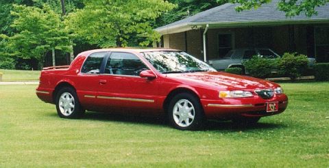
1997 Mercury Cougar/
Photo
supermotors.net/registry/media/745647
C250 Instrument Cluster Connector Pinout - 16-Pin Wiring Diagram & Functions
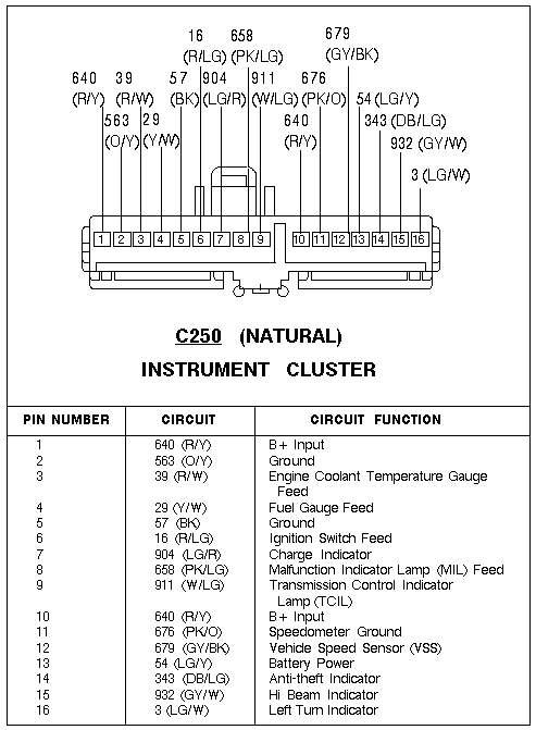
Connector pinout for the C250 instrument cluster listing 16 pins, color-coded circuits, and circuit functions.
Part of 1989-1997 Mercury Cougar Wiring Diagrams
This document is a connector pinout diagram and table for connector C250 (natural color), which plugs into the instrument cluster. The upper portion shows a drawing of the 16-pin connector with each cavity numbered 1 through 16 and labeled with its circuit number and wire color code (e.g., 640 R/Y, 563 O/Y, 679 GY/BK). Below the drawing, a three-column table lists each pin number, its circuit designation with wire color abbreviation, and the circuit function. Functions covered include B+ input (pins 1 and 10), grounds (pins 2 and 5), engine coolant temperature gauge feed (pin 3), fuel gauge feed (pin 4), ignition switch feed (pin 6), charge indicator (pin 7), Malfunction Indicator Lamp (MIL) feed (pin 8), Transmission Control Indicator Lamp (TCIL) (pin 9), speedometer ground (pin 11), Vehicle Speed Sensor (VSS) signal (pin 12), battery power (pin 13), anti-theft indicator (pin 14), high beam indicator (pin 15), and left turn indicator (pin 16). A reader can use this diagram to identify each instrument cluster connector pin, its wire color, and its function for diagnosing gauge, indicator lamp, or speedometer problems. The document itself does not state a year, make, or model.
Is this accurate? Sign in to help verify it.
Frequently asked questions
- What connector is shown in this diagram?
- Connector C250 (natural color), the 16-pin connector for the instrument cluster.
- Which pin on C250 carries the Vehicle Speed Sensor (VSS) signal?
- Pin 12, circuit 679 with a gray/black (GY/BK) wire.
- Which pins on the C250 instrument cluster connector are grounds?
- Pin 2 (circuit 563, O/Y) and pin 5 (circuit 57, BK) are grounds; pin 11 (circuit 676, PK/O) is the speedometer ground.
- What wire feeds the fuel gauge at the instrument cluster?
- Pin 4, circuit 29 with a yellow/white (Y/W) wire, is the fuel gauge feed.
- Where does the Malfunction Indicator Lamp (MIL) connect at the cluster?
- Pin 8, circuit 658 with a pink/light green (PK/LG) wire, is the MIL feed.
Comments
More from this build

No comments yet.