Home/
Registry/
Mercury/
Cougar/
1989-1997/
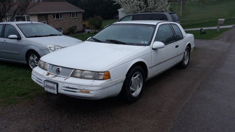
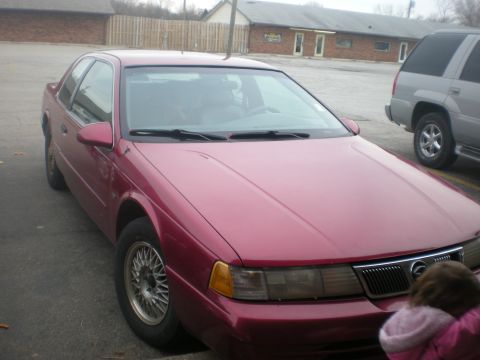
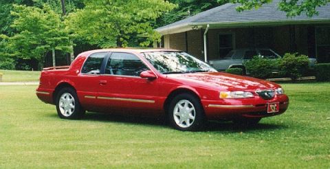
1997 Mercury Cougar/
Photo
supermotors.net/registry/media/745648
Ford C251 Instrument Cluster Connector Pinout - 16-Pin Wiring Diagram

Connector pinout for the C251 instrument cluster listing 16 pins, color-coded circuits, and circuit functions.
Part of 1989-1997 Mercury Cougar Wiring Diagrams
This document is a connector pinout diagram for connector C251 (Natural color), the instrument cluster connector, apparently from a Ford factory wiring/EVTM reference. The upper portion shows a drawing of the 16-pin connector body with each cavity numbered 1 through 16 and labeled with its circuit number and wire color code (e.g., pin 1 = circuit 2, White/Light Blue; pin 6 = circuit 397, Black/White). Below the drawing, a three-column table lists Pin Number, Circuit (number and color), and Circuit Function for all 16 pins. Functions covered include the right turn indicator, low coolant indicator feed, air bag indicator feed, brake indicator feed, anti-lock (ABS) indicator feed, tachometer feed, low engine oil indicator, illumination lamps feed, fasten belts indicator, engine oil pressure gauge feed, two B+ power inputs (circuit 640, R/Y on pins 9 and 13), and four grounds (pins 6, 8, 14, 16). A reader can use this to identify which wire and color at the instrument cluster connector serves each gauge or warning lamp, useful for diagnosing cluster, gauge, or indicator lamp problems, or for cluster swaps and custom wiring. The document itself does not state a year, make, or model; the filename suggests it may pertain to a 1995 Mustang instrument panel.
Is this accurate? Sign in to help verify it.
Frequently asked questions
- What is connector C251?
- C251 is the Natural-colored 16-pin instrument cluster connector shown in this diagram, with each pin's circuit number, wire color, and function listed.
- Which pins on the instrument cluster connector are grounds?
- Pins 6 (397, BK/W), 8 (651, BK/Y), 14 (875, BK/LB), and 16 (57, BK) are grounds.
- Which pins provide B+ power to the instrument cluster?
- Pins 9 and 13, both circuit 640 with Red/Yellow (R/Y) wires, are B+ inputs.
- What wire feeds the tachometer at the cluster connector?
- Pin 7, circuit 11, a Tan/Yellow (T/Y) wire, is the Tachometer Feed.
- Which pin is the anti-lock (ABS) indicator feed?
- Pin 5, circuit 603, a Dark Green (DG) wire, is the Anti-Lock Indicator Feed.
Comments
More from this build


No comments yet.