4 Bar Linkage Calculator v3.0 - 4-Link Suspension Geometry (Ford Ranger Build)
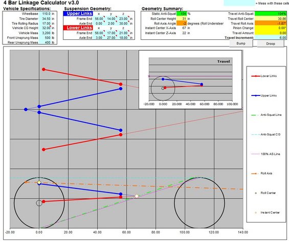
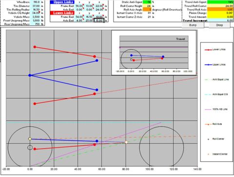
Suspension 4-bar linkage calculator screenshot plotting upper and lower link geometry, roll axis and anti-squat lines against the tires.
This document is a screenshot of a spreadsheet-based "4 Bar Linkage Calculator v3.0" used for designing a 4-link suspension, uploaded to the gallery of a 1987 Ford Ranger. The calculator's input sections include Vehicle Specifications (wheelbase 110.0 in, tire diameter 34.50 in, tire rolling radius 17.00 in, vehicle CG height 32.00 in, vehicle mass 3,200 lb, front unsprung mass 500 lb, rear unsprung mass 400 lb) and Suspension Geometry with x/y/z coordinates for the frame and axle ends of both the upper links (frame end 56.00, 14.00, 23.00; axle end 0.00, 2.00, 30.00) and lower links (frame end 56.00, 17.00, 21.00; axle end 3.00, 27.00, 18.00). The Geometry Summary output shows 104% static anti-squat, 31 in roll center height, -2 degrees roll axis angle (roll understeer), and instant center at 67 in (X-axis) and 22 in (Z-axis). Travel outputs include 104% travel anti-squat, 30.86 travel roll center, -1.87° travel roll axis, 0.00° pinion change, 0.00 travel amount, and 6.00 travel increment, with Bump and Droop buttons. A large side-view plot and a smaller Travel inset graph the links, anti-squat line, anti-squat CG, 100% AS line, roll axis, roll center, and instant center. A reader can learn a specific set of 4-link geometry values and resulting suspension characteristics.
Is this accurate? Sign in to help verify it.
Frequently asked questions
- What is the static anti-squat percentage shown in this 4-link calculator?
- The Geometry Summary shows a Static Anti-Squat of 104%, and the Travel Anti-Squat is also 104%.
- What vehicle specifications are entered in the calculator?
- Wheelbase 110.0 in, tire diameter 34.50 in, tire rolling radius 17.00 in, vehicle CG height 32.00 in, vehicle mass 3,200 lb, front unsprung mass 500 lb, and rear unsprung mass 400 lb.
- What are the upper link coordinates in this setup?
- Upper links: frame end at x=56.00, y=14.00, z=23.00 in; axle end at x=0.00, y=2.00, z=30.00 in.
- What roll center height and roll axis angle does this geometry produce?
- Roll center height is 31 in and the roll axis angle is -2 degrees (labeled as roll understeer); the travel roll center is 30.86 and travel roll axis is -1.87°.
- Where is the instant center located?
- The instant center is at 67 in on the X-axis and 22 in on the Z-axis.
Comments
More from this build
No comments yet.