Ford Bronco Voltmeter Wiring Diagram - Keyed Ignition Tap & Fuse Block Hookup
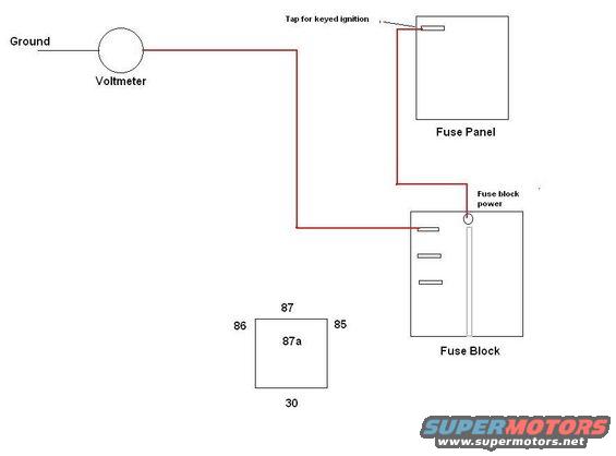
User-drawn relay test schematic showing a voltmeter to ground, a keyed-ignition tap at the fuse panel, fuse-block power, and a standard ISO relay pinout (terminals 30, 85, 86, 87, 87a).
Part of 1992-1996 Ford Bronco Schematics
This is a simple hand-drawn wiring schematic (digital drawing) showing how to wire an aftermarket voltmeter into a vehicle's electrical system. The voltmeter, drawn as a circle at the upper left, has one terminal going to Ground and the other terminal (in red wire) routed to an auxiliary fuse block. The auxiliary fuse block, shown at lower right with three fuse slots and a power bus, receives its 'fuse block power' feed from a tap on the factory fuse panel labeled 'Tap for keyed ignition,' meaning the voltmeter circuit is powered only when the ignition key is on. A separate square diagram at the bottom center shows a standard automotive relay pin layout with terminals 87 (top), 86 (left), 85 (right), 87a (center), and 30 (bottom), presumably as a reference for related relay wiring. The document contains no wire colors (other than the red power path drawn), no fuse amperage values, no part numbers, and no year/model identification. A reader can learn the basic power routing concept: tap keyed ignition power at the fuse panel, feed an auxiliary fuse block, then supply the voltmeter from that fuse block, with the other voltmeter lead grounded.
Is this accurate? Sign in to help verify it.
Frequently asked questions
- Where does the voltmeter get its power in this diagram?
- From an auxiliary fuse block, which is fed by a tap on the factory fuse panel labeled 'Tap for keyed ignition,' so the voltmeter is powered only with the key on.
- How is the voltmeter connected?
- One terminal of the voltmeter goes to Ground; the other terminal is wired (shown in red) to the auxiliary fuse block.
- What relay pin layout is shown in the diagram?
- A square relay diagram with pin 87 on top, 86 on the left, 85 on the right, 87a in the center, and 30 on the bottom.
- Does the diagram specify fuse amperages or wire colors?
- No. It shows only the routing (with the power wire drawn in red) and labels; no amperage ratings, wire color codes, or part numbers are given.
Comments
More from this build





No comments yet.