SuperMotors SuperMotors SUPERMOTORS Search: try “orange Bronco on 35s”
Home/ Registry/ Ford/ Bronco/ 1992-1996/ “Big '92”/ Photo supermotors.net/registry/media/84634

Ford Bronco Gasoline Engine Vacuum Hose Routing Diagram - Hose Colors & Ports

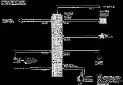
Vacuum routing diagram for gasoline engines showing color-coded hoses from manifold to brake booster, MAP sensor, and speed control
Vacuum routing diagram for gasoline engines showing color-coded hoses from manifold to brake booster, MAP sensor, and speed controlOriginal file
Vacuum routing diagram for gasoline engines showing color-coded hoses from manifold to brake booster, MAP sensor, and speed control

Reference · 1992-1996 BroncoAll 40 vacuum routing diagrams
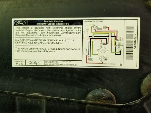
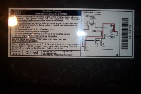
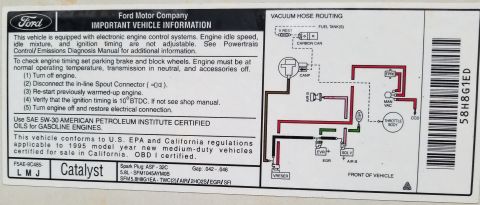
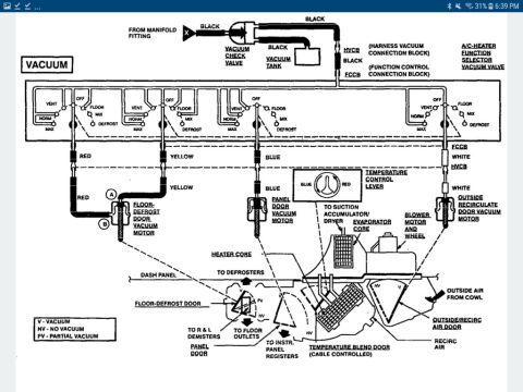
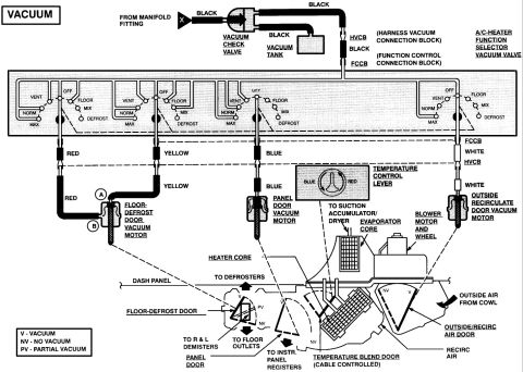
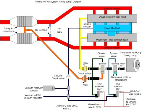
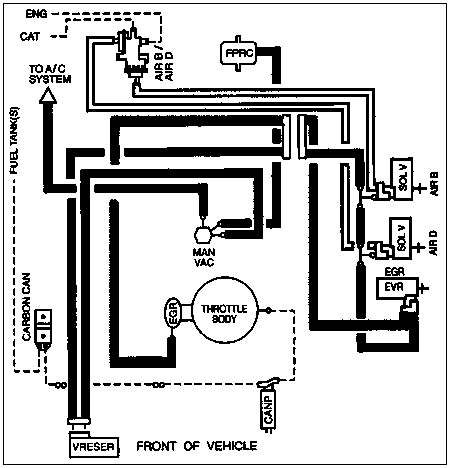
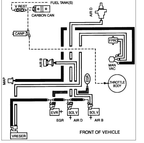
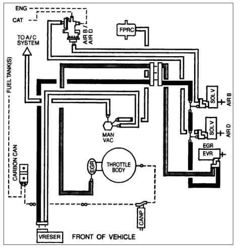
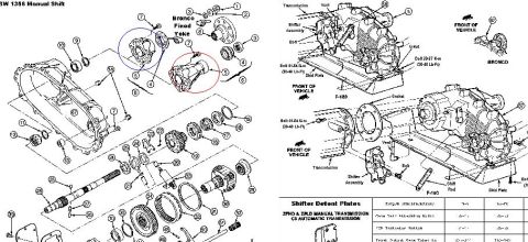
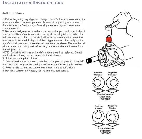
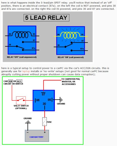
Ford Bronco Gasoline Engine Vacuum Hose Routing Diagram - Hose Colors & Ports 1992 Ford Bronco PCV Valve Hose Routing Sketch - Simple Diagram 1995 Ford Bronco 5.8L Emissions/VECI Label - Vacuum Hose Routing Diagram 1996 Ford Bronco 5.0L VECI Label - Vacuum Hose Routing Diagram & Spark Plug Gap 1995 Ford 5.8L OEM Emissions & Vacuum Hose Routing Diagram Decal (Bronco) 1995 Ford Bronco 5.8L Emissions & Vacuum Hose Routing Decal - VECI Label 1996 Ford Bronco A/C-Heater Vacuum Routing Diagram - HVAC Door Vacuum Motors Ford Bronco A/C-Heater Vacuum Diagram - HVAC Vacuum Line Routing & Door Motors Ford Thermactor Air System (Smog Pump) Diagram - Vacuum & Wiring Routing 1995 Ford Bronco Vacuum Hose Routing Diagram - EGR, AIR, CANP, FPRC Lines Ford Bronco 351 Vacuum Hose Routing Diagram - EGR, CANP, AIR B/D, MAP, VRESER 1994 Ford Bronco Vacuum Hose Routing Diagram - EGR, Thermactor Air, CANP, FPRC 40vacuum routing diagrams1992-1996 Ford Bronco More reference Winch Wiring Connections Diagram (Figure E) - Solenoid, Battery & Circuit BreakerWiring diagram Ford BW 1356 Manual Shift Transfer Case Exploded Diagram - Bronco & F-150Exploded parts 4WD truck alignment sleeve install instructions with knuckle illustration and camber/caster top viewsService procedure Homelite Textron SAFE-T-TIP anti-kickback chain saw device installation and use instruction sheetManual page 5-Pin SPDT Relay Diagram - Pin 30/85/86/87/87a Wiring & CarPC ACC/IGN SetupSchematic Ford Bronco Power Distribution Box Diagram - Relay Layout & Fuse PositionsFuse chart 1994 Ford Bronco Door Data Spec Plate - VIN, GVWR, Axle & Paint CodesSpec plate Smittybilt XRC Gen 3 Winch Box - 9.5K/12K Recovery Winch Features & CalloutsBrochure Brake Booster to Master Cylinder Adapter Plate Blueprint - Ford Bronco SwapBlueprint Rod Bolt Stretch Monitoring Chart - 8-Rod V8 Connecting Rod Bolt Record SheetTorque spec

Vacuum hose routing diagram for gasoline engines, labeling color-coded lines to the brake booster, MAP sensor, air cleaner, and speed control.

Part of 1992-1996 Ford Bronco Vacuum Routing Diagrams

AI caption · Photo 99 of 2193

This document is a vacuum hose routing diagram for gasoline engines, showing how vacuum lines connect from a central vacuum manifold (tree) to various components. The manifold receives vacuum from a manifold fitting (vacuum source) via a black hose, near which the Manifold Absolute Pressure (MAP) sensor connects. From the manifold, a pink hose runs to the solenoids, a black hose runs to the vacuum check valve, a black/yellow hose runs to the air cleaner, a black hose runs to the automatic transmission option (C6), a black/brown hose runs to the speed control, a red hose runs to the distributor, and a hose marked black with yellow letters runs to the vacuum brake booster. A note states that the auxiliary heater vacuum motor and water valve are supplied with the auxiliary heater, with or without auxiliary A/C. The diagram uses hose color coding to identify each circuit, making it useful for verifying correct vacuum line routing when diagnosing vacuum leaks, speed control issues, brake booster problems, or transmission modulator (C6) vacuum supply. The document does not state a specific year, model, or engine displacement, only that it applies to gasoline engines.

Is this accurate? Sign in to help verify it.

Frequently asked questions

What color is the vacuum hose to the brake booster?
The hose to the vacuum brake booster is identified as black with yellow letters.
Which vacuum line goes to the speed control?
A black/brown hose from the vacuum manifold runs to the speed control (marked with an 'S').
What color hose runs to the distributor?
A red hose runs to the distributor.
Where does the pink vacuum hose go?
The pink hose from the top of the vacuum manifold goes to the solenoids.
Does the diagram mention the automatic transmission?
Yes, a black hose connects to the automatic transmission option, noted as the C6 transmission.

Comments

No comments yet.

More 1992-1996 Broncos