5-Pin SPDT Relay Diagram - Pin 30/85/86/87/87a Wiring & CarPC ACC/IGN Setup
Reference · 1992-1996 BroncoAll 95 schematics
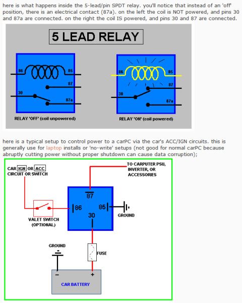









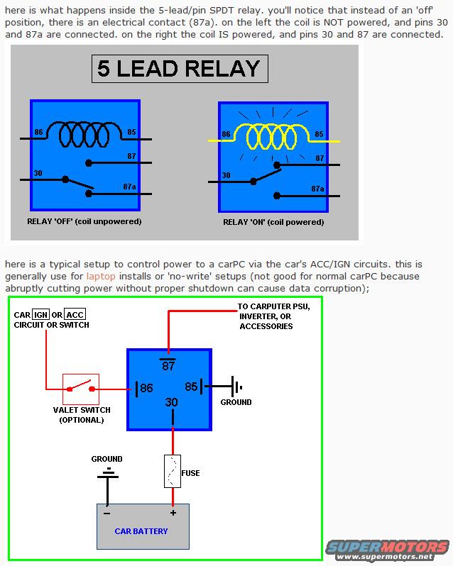
Schematic of a 5-lead SPDT relay in off and on states with an example wiring setup controlling carPC power via ACC/IGN circuits.
Part of 1992-1996 Ford Bronco Schematics
This document is a two-part illustrated tutorial on 5-lead/pin SPDT automotive relays. The first section, titled "5 LEAD RELAY," shows two internal schematic views of the relay: on the left, with the coil unpowered (RELAY 'OFF'), pins 30 and 87a are connected; on the right, with the coil powered (RELAY 'ON'), pins 30 and 87 are connected. Coil terminals are labeled 86 and 85. The text explains that instead of a true 'off' position, the SPDT relay has an alternate electrical contact (87a). The second section shows a typical wiring setup for controlling power to a carPC (carputer) using the vehicle's ACC/IGN circuit: the car IGN or ACC circuit (optionally through a valet switch) feeds pin 86, pin 85 goes to ground, pin 30 connects through a fuse to the car battery positive terminal, and pin 87 feeds the carputer PSU, inverter, or accessories. The battery negative is grounded. The text notes this arrangement is generally used for laptop installs or 'no-write' setups and warns it is not good for a normal carPC because abruptly cutting power without proper shutdown can cause data corruption. Readers learn SPDT relay pin functions (30, 85, 86, 87, 87a) and a practical switched-power wiring example.
Is this accurate? Sign in to help verify it.
Frequently asked questions
- Which pins are connected when a 5-pin SPDT relay coil is unpowered?
- When the coil is NOT powered (relay 'OFF'), pins 30 and 87a are connected.
- Which pins are connected when the relay coil is powered?
- When the coil IS powered (relay 'ON'), pins 30 and 87 are connected.
- How is the relay wired to control power to a carPC from the ACC/IGN circuit?
- The car IGN or ACC circuit (optionally through a valet switch) goes to pin 86, pin 85 goes to ground, pin 30 goes through a fuse to the car battery positive terminal, and pin 87 goes to the carputer PSU, inverter, or accessories.
- Why is this switched-power setup not recommended for a normal carPC?
- Because abruptly cutting power without a proper shutdown can cause data corruption; it is generally used for laptop installs or 'no-write' setups.
- What does pin 87a do on a 5-lead SPDT relay?
- Instead of an 'off' position, the relay has an electrical contact (87a) that is connected to pin 30 when the coil is unpowered.






No comments yet.