SuperMotors SuperMotors SUPERMOTORS Search: try “orange Bronco on 35s”
Home/ Registry/ Ford/ Bronco/ 1992-1996/ “Big '92”/ Photo supermotors.net/registry/media/916240

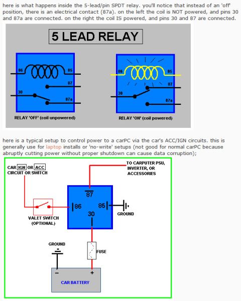
Bosch-Style Automotive Relay Diagram - 4-Pin SPST & 5-Pin SPDT Pinout Explained

4-lead relay schematic showing coil unpowered and powered states with pins 30, 85, 86, 87 and a 5-lead bottom view
4-lead relay schematic showing coil unpowered and powered states with pins 30, 85, 86, 87 and a 5-lead bottom viewOriginal file
4-lead relay schematic showing coil unpowered and powered states with pins 30, 85, 86, 87 and a 5-lead bottom view

Reference · 1992-1996 BroncoAll 95 schematics
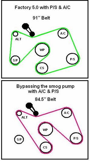
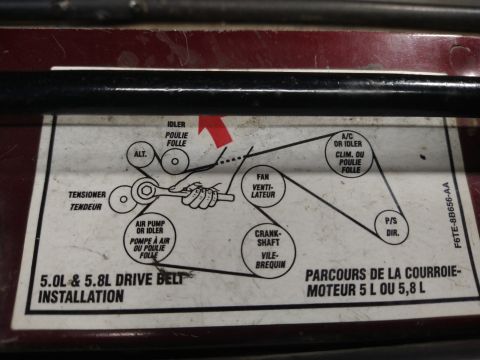
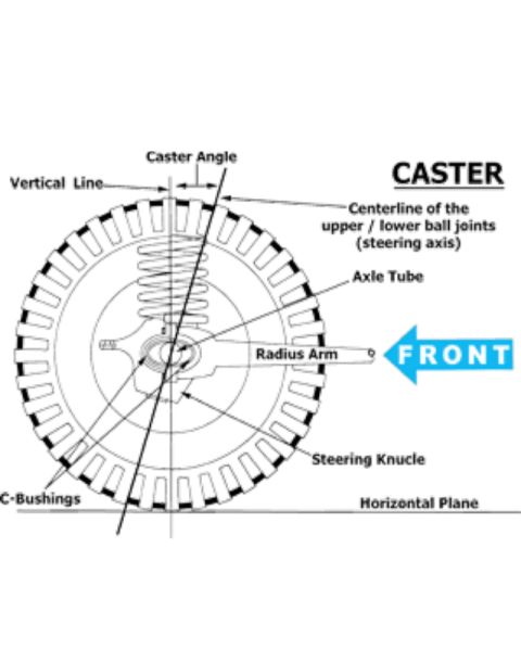
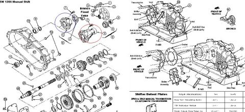
5-Pin SPDT Relay Diagram - Pin 30/85/86/87/87a Wiring & CarPC ACC/IGN Setup Bosch-Style Automotive Relay Diagram - 4-Pin SPST & 5-Pin SPDT Pinout Explained Ford Bronco/F-Series G101 PCM Ground & Engine Bay Connector Location Diagram Ford Bronco Track Bar Axle Mount Diagram - Bolt, Tab & Bracket Layout Ford Bronco Track Bar Axle Mount Diagram - Bolt, Tab & Mount Locations Ford Bronco Track Bar Mount & Axle Housing Diagram - Suspension Schematic Ford Bronco Voltmeter Wiring Diagram - Keyed Ignition Tap & Fuse Block Hookup Ford EEC 60-Pin PCM Connector Pin Numbering Diagram (EEC-IV Pinout Layout) 1993 Ford V8 Serpentine Belt Routing Diagram - Pulley Layout (Q2601-E) Ford 5.0 Serpentine Belt Routing Diagram - Factory & Smog Pump Bypass Belt Sizes 1996 Ford Bronco 5.0L & 5.8L Serpentine Belt Routing Diagram (F6TE-8B656-AA) Caster Angle Diagram - Ford Solid Axle Radius Arm & C-Bushing Steering Geometry 95schematics1992-1996 Ford Bronco More reference Winch Wiring Connections Diagram (Figure E) - Solenoid, Battery & Circuit BreakerWiring diagram Ford BW 1356 Manual Shift Transfer Case Exploded Diagram - Bronco & F-150Exploded parts 4WD truck alignment sleeve install instructions with knuckle illustration and camber/caster top viewsService procedure Homelite Textron SAFE-T-TIP anti-kickback chain saw device installation and use instruction sheetManual page Ford Bronco Gasoline Engine Vacuum Hose Routing Diagram - Hose Colors & PortsVacuum routing Ford Bronco Power Distribution Box Diagram - Relay Layout & Fuse PositionsFuse chart 1994 Ford Bronco Door Data Spec Plate - VIN, GVWR, Axle & Paint CodesSpec plate Smittybilt XRC Gen 3 Winch Box - 9.5K/12K Recovery Winch Features & CalloutsBrochure Brake Booster to Master Cylinder Adapter Plate Blueprint - Ford Bronco SwapBlueprint Rod Bolt Stretch Monitoring Chart - 8-Rod V8 Connecting Rod Bolt Record SheetTorque spec

Schematic explaining a 4-lead SPST automotive relay in off and on states, plus a bottom view of a standard 5-lead Bosch SPDT relay.

Part of 1992-1996 Ford Bronco Schematics

AI caption · Photo 1075 of 2193

This document is an educational schematic explaining the internal operation of standard automotive relays. The first illustration, titled '4 LEAD RELAY,' shows two side-by-side internal diagrams of a 4-lead/pin SPST relay: on the left the coil (pins 86 and 85) is unpowered and the switch contact from pin 30 is open ('RELAY OFF'); on the right the coil is powered, the switch closes, and pins 30 and 87 become connected ('RELAY ON'). The accompanying text explains that when the coil is not powered, pin 30 is not connected to anything and the relay is in the 'off' position. The second illustration shows the bottom view pin layout of a standard 5-lead Bosch-style automotive SPDT relay, with pins labeled 87, 86, 87a, 85, and 30, noting the only difference from the 4-lead relay is the addition of the 87a lead/pin. A reader can learn how relay pins 30, 85, 86, 87, and 87a function, how the coil switches the contacts, and the physical pin arrangement of a typical Bosch-style relay as seen from the bottom.

Is this accurate? Sign in to help verify it.

Frequently asked questions

What happens inside a 4-pin SPST relay when the coil is powered?
When the coil is powered, the switch changes position and pins 30 and 87 are connected. When the coil is not powered, pin 30 is not connected to anything, so the relay is in the 'off' position.
Which pins are the coil on a standard automotive relay?
The coil is connected across pins 86 and 85, as shown in the internal diagrams.
What is the difference between a 4-lead and a 5-lead Bosch-style relay?
The only difference is the addition of the 87a lead/pin on the 5-lead SPDT relay.
What is the pin layout on the bottom of a typical Bosch-style relay?
Viewed from the bottom: pin 87 at top center, 86 on the left, 87a in the center, 85 on the right, and 30 at bottom center.


Comments

No comments yet.

More 1992-1996 Broncos