Trailer Coupler Warning Plate - GVWR Ratings for 50mm & 2-Inch Ball, Tongue Load
Reference · 1992-1996 BroncoAll 103 data & spec plates

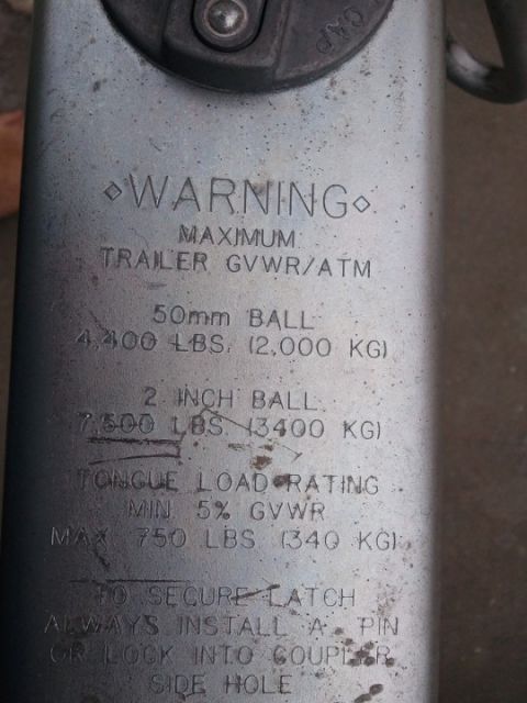











Cast warning/rating plate on a trailer hitch listing maximum trailer GVWR/ATM and tongue load specifications.
Part of 1992-1996 Ford Bronco Data & Spec Plates
This is a photograph of a stamped warning/specification plate on a trailer coupler (the album also contains a related "Trailer Brake actuator" image, suggesting this is a surge-brake style coupler). The plate states the maximum trailer GVWR/ATM ratings for two ball sizes: with a 50mm ball, the maximum is 4,400 lbs (2,000 kg); with a 2-inch ball, the maximum is 7,500 lbs (3,400 kg). It also specifies the tongue load rating as a minimum of 5% of GVWR and a maximum of 750 lbs (340 kg). Finally, it instructs that to secure the latch, a pin or lock must always be installed into the coupler side hole. No manufacturer name, part number, model number, or date is visible in this photo. The document does not itself reference any tow vehicle; it was uploaded to a 1994 Ford Bronco gallery, presumably as documentation of trailer equipment used with that vehicle. A reader can learn the coupler's weight capacity by ball size, allowable tongue weight range, and the required latch-securing procedure.
Is this accurate? Sign in to help verify it.
Frequently asked questions
- What is the maximum trailer GVWR with a 2-inch ball on this coupler?
- 7,500 lbs (3,400 kg).
- What is the maximum trailer GVWR with a 50mm ball?
- 4,400 lbs (2,000 kg).
- What is the tongue load rating for this coupler?
- Minimum 5% of GVWR, maximum 750 lbs (340 kg).
- How should the coupler latch be secured?
- Always install a pin or lock into the coupler side hole to secure the latch.






No comments yet.